
Page 123 - 35_DS702_E_2014_Lightning_Protection_Guide
P. 123
Earth resistance R A (Ω) LONGITUDINAL DIRECTION
Earth potential U E (%) 80 100 cm V
100 100 a
60
ρ E = 100 Ωm 40 50 cm t = 0 cm t
ρ E = 200 Ωm 20
50 ρ E = 500 Ωm
Distance a (m) from earth electrode
TRANSVERSE DIRECTION
a
Earth potential U E (%) 80 100 cm V
100
60
50 100 40 50 cm t
Length I of the stretched surface earth electrode (m) 20 t = 0 cm
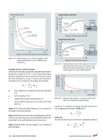
Figure 5.5.7 Earth resistance R A as a function of length I of the
surface earth electrode in case of different earth Distance a (m) from earth electrode
resistivities ρ E
Figure 5.5.8 Earth potential U E between the supply line of the earth
electrode and the earth surface as a function of the
distance from the earth electrode in case of an strip
Straight surface earth electrode earth electrode (8 m long) in different depths
Surface earth electrodes are typically embedded horizontally in
the ground at a depth of 0.5 to 1 m. Since the soil layer above
the earth electrode dries out in summer and freezes in winter, %
the earth resistance R A of such a surface earth electrode is 100
calculated as if it is installed on the surface of the ground: Max. step voltage of the total voltage 80
l 60
R = E ln 40
A
l r 20
R A Earth resistance of a stretched surface earth electrode
in Ω 0.5 1 1.5 2 m
Burial depth
ρ E Earth resistivity in Ωm
l Length of the surface earth electrode in m Figure 5.5.9 Maximum step voltage U S as a function of the burial
depth for a stretched strip earth electrode
r Quarter width of strip steel in m or radius of the round
wire in m
In practice, it is sufficient to calculate the earth resistance us-
Figure 5.5.7 shows the earth resistance R A as a function of ing the approximate formula in Table 5.5.1:
the length of the earth electrode. 2
R = E
Figure 5.5.8 shows the transverse and longitudinal earth po- A l
tential U E for an 8 m long strip earth electrode. The effect of the Earth rod
burial depth on the earth potential can be clearly seen. The earth resistance R A of an earth rod is calculated as follows:
2l
Figure 5.5.9 illustrates the step voltage U S as a function of R = E ln
the burial depth. A 2 l r
122 LIGHTNING PROTECTION GUIDE www.dehn-international.com