
Page 126 - 35_DS702_E_2014_Lightning_Protection_Guide
P. 126
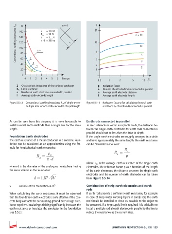
Conventional earthing impedance R st  160  n = 1  = 150 Ω  n = 4  l  20 p 5  n = 20
              Ω
                         Z
                         R A   = 10 Ω
            140
                            = 1 ... 4
                         n
                         n · l  = 300 m
                                                         10
            120
                                                                                    10
            100
             80
             60
             40    2  3                                   3 2                        5 3
                      4                                                              2
             20                                           1
              0
                0  1  2  3  4   5  6  Time µs                                            a
                                                            0.5   1     2      5     10
                                                                                         l
           Z   Characteristic impedance of the earthing conductor  p  Reduction factor
           R A   Earth resistance                          n   Number of earth electrodes connected in parallel
           n   Number of earth electrodes connected in parallel   a   Average earth electrode distance
           l   Average earth electrode length              l   Average earth electrode length
       Figure 5.5.13  Conventional earthing impedance R st  of single-arm or   Figure 5.5.14  Reduction factor p for calculating the total earth
                multiple-arm surface earth electrodes of equal length  resistance R A  of earth rods connected in parallel


       As can be seen from this diagram, it is more favourable to   Earth rods connected in parallel
       install a radial earth electrode than a single arm for the same   To keep interactions within acceptable limits, the distances be-
       length.                                      tween the single earth electrodes for earth rods connected in
                                                    parallel should not be less than the drive-in depth.
       Foundation earth electrodes                  If the single earth electrodes are roughly arranged in a circle
       The earth resistance of a metal conductor in a concrete foun-  and have approximately the same length, the earth resistance
       dation can be calculated as an approximation using the for-  can be calculated as follows:
       mula for hemispherical earth electrodes:                            R
                                                                     R =    A'
                       R =     E                                      A     p
                        A
                               d
                                                    where R A'  is the average earth resistance of the single earth
       where d is the diameter of the analogous hemisphere having   electrodes. The reduction factor p as a function of the length
       the same volume as the foundation:           of the earth electrodes, the distance between the single earth
                                                    electrodes and the number of earth electrodes can be taken
                     d = 1.57  3 V                  from Figure 5.5.14.

       V    Volume of the foundation in m 3         Combination of strip earth electrodes and earth
                                                    rods
       When  calculating  the  earth  resistance,  it  must  be  observed   If earth rods provide a sufficient earth resistance, for example
       that the foundation earth electrode is only effective if the con-  in case of deep water carrying layers in sandy soil, the earth
       crete body contacts the surrounding ground over a large area.   rod should be installed as close as possible to the object to
       Water-repellent, insulating shielding significantly increases the   be protected. If a long supply line is required, it is advisable to
       earth resistance or insulates the conductor in the foundation   install a multiple radial earth electrode in parallel to the line to
       (see 5.5.2).                                 reduce the resistance as the current rises.


            www.dehn-international.com                             LIGHTNING PROTECTION GUIDE  125