
Page 122 - 35_DS702_E_2014_Lightning_Protection_Guide
P. 122
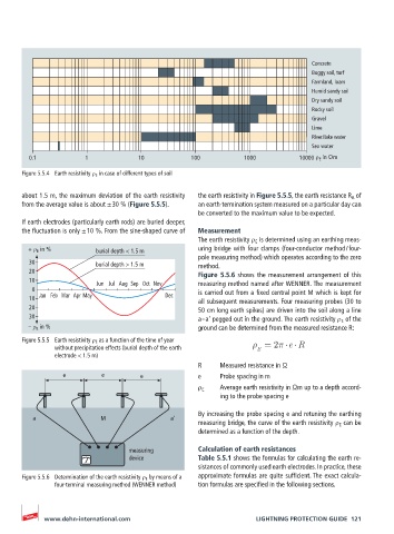
Concrete
                                                                                  Boggy soil, turf
                                                                                  Farmland, loam
                                                                                  Humid sandy soil
                                                                                  Dry sandy soil
                                                                                  Rocky soil
                                                                                  Gravel
                                                                                  Lime
                                                                                  River / lake water
                                                                                  Sea water
         0.1           1             10            100          1000          10000  ρ E  in Ωm

       Figure 5.5.4  Earth resistivity ρ E  in case of different types of soil

       about 1.5 m, the maximum deviation of the earth resistivity   the earth resistivity in Figure 5.5.5, the earth resistance R A  of
       from the average value is about ± 30 % (Figure 5.5.5).  an earth-termination system measured on a particular day can
                                                    be converted to the maximum value to be expected.
       If earth electrodes (particularly earth rods) are buried deeper,
       the fluctuation is only ± 10 %. From the sine-shaped curve of   Measurement
                                                    The earth resistivity ρ E  is determined using an earthing meas-
        + ρ E  in %       burial depth < 1.5 m      uring bridge with four clamps (four-conductor method / four-
                                                    pole measuring method) which operates according to the zero
         30               burial depth > 1.5 m      method.
         20                                         Figure 5.5.6 shows the measurement arrangement of this
         10               Jun Jul Aug Sep Oct Nov   measuring method named after WENNER. The measurement
         0                                          is carried out from a fixed central point M which is kept for
           Jan Feb Mar Apr May              Dec
         10                                         all subsequent measurements. Four measuring probes (30 to
         20                                         50 cm long earth spikes) are driven into the soil along a line
         30                                         a – a' pegged out in the ground. The earth resistivity ρ E  of the
        -- ρ E  in %                                ground can be determined from the measured resistance R:
       Figure 5.5.5  Earth resistivity ρ E  as a function of the time of year
               without precipitation effects (burial depth of the earth   E  = 2  e R
               electrode < 1.5 m)
                                                    R     Measured resistance in Ω
                 e         e         e              e     Probe spacing in m
                                                    ρ E    Average earth resistivity in Ωm up to a depth accord-
                                                          ing to the probe spacing e
                                                    By increasing the probe spacing e and retuning the earthing
          a                M                 a’
                                                    measuring bridge, the curve of the earth resistivity ρ E  can be
                                                    determined as a function of the depth.

                                  measuring         Calculation of earth resistances
                                  device            Table 5.5.1 shows the formulas for calculating the earth re-
                                                    sistances of commonly used earth electrodes. In practice, these
       Figure 5.5.6  Determination of the earth resistivity ρ E  by means of a   approximate formulas are quite sufficient. The exact calcula-
               four-terminal measuring method (WENNER method)  tion formulas are specified in the following sections.


            www.dehn-international.com                             LIGHTNING PROTECTION GUIDE  121