
Page 160 - 35_DS702_E_2014_Lightning_Protection_Guide
P. 160
mandatory to prevent puncture of the insulation and creeping creeping flashover along the surface of the insulation. Impulse
flashover along the insulating clearance. withstand voltage tests under wet conditions according to
A harmonised system solution such as the CUI Conductor pre- IEC 60060-1 (EN 60060-1) have shown that the CUI Conductor
vents puncture and creeping flashover and thus ensures pro- is both resistant to puncture and creeping flashover in case of
tection against touch voltage. impulse voltages up to 100 kV (1.2/50 µs). During these wet
tests, a defined quantity of water with a specific conductivity is
Design of CUI Conductors sprayed onto the conductor at an angle of about 45 ° (Figure
CUI Conductors consist of an inner copper conductor with a 5.7.1.3).
2
cross-section of 50 mm and is coated with an insulation layer
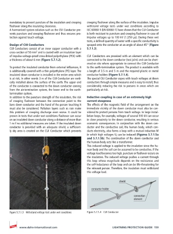
of impulse-voltage-proof cross-linked polyethylene (PEX) with CUI Conductors are prewired with an element which can be
a thickness of about 6 mm (Figure 5.7.1.2). connected to the down conductor (test joint) and can be short-
ened on site where appropriate to connect the CUI Conductor
To protect the insulated conductor from external influences, it to the earth-termination system. The product is available with
is additionally covered with a thin polyethylene (PE) layer. The a length of 3.5 m and 5 m and the required plastic or metal
insulated down conductor is installed in the entire area which conductor holders (Figure 5.7.1.4).
is at risk, in other words 3 m of the CUI Conductor are verti- The special CUI Conductor copes with touch voltages at down
cally installed above the surface of the earth. The upper end conductors through simple measures and is easy to install, thus
of the conductor is connected to the down conductor coming considerably reducing the risk to persons in areas which are
from the air-termination system, the lower end to the earth- particularly at risk.
termination system.
In addition to the puncture strength of the insulation, the risk Inductive coupling in case of an extremely high
of creeping flashover between the connection point to the current steepness
bare down conductor and the hand of the person touching it The effects of the magnetic field of the arrangement on the
must also be considered. Pollution layers such as rain make immediate vicinity of the down conductor must also be con-
this problem of creeping discharge even worse. It could be sidered to protect persons from touch voltage. In large instal-
proven in tests that under wet conditions flashover can occur lation loops, for example, voltages of several 100 kV can occur
on an insulated down conductor along a distance of more than in close proximity to the down conductor, resulting in serious
1 m if no additional measures are taken. If the insulated down economic consequences. In conjunction with the down con-
conductor is provided with an adequate shield, a sufficient- ductor and the conductive soil, the human body, which con-
ly dry area is created on the CUI Conductor which prevents ducts electricity, also forms a loop with a mutual induction M
in which high voltages U i can be induced (Figures 5.7.1.5a
and 5.7.1.5b). The combination of the down conductor and
the human body acts like a transformer.
This induced voltage is applied to the insulation since the hu-
man body and the soil can be assumed to be conductive. If the
voltage load becomes too high, puncture or flashover occurs on
the insulation. The induced voltage pushes a current through
this loop whose magnitude depends on the resistances and
the self-inductance of the loop and can be life-threatening for
the relevant person. Therefore, the insulation must withstand
this voltage load.
shield
conductor holder
connection
element
Figure 5.7.1.3 Withstand voltage test under wet conditions Figure 5.7.1.4 CUI Conductor
www.dehn-international.com LIGHTNING PROTECTION GUIDE 159