
Page 161 - 35_DS702_E_2014_Lightning_Protection_Guide
P. 161
step / body voltage can be included in the simulation. However,
a) b) simulations with unloaded step voltages lead to excessive and
supposedly unacceptable voltage values.
To be able to assess the simulation results, a step voltage value
∆i/∆t ∆i/∆t is available, which is secured by extensive literature research.
A prerequisite for the optimisation of earth-termination sys-
U i tems with regard to step voltage aspects is to define a permis-
sible step / body voltage which does not cause health damage.
h Step voltage limit values
M
Literature provides information on technical a.c. voltages as
well as hand-to-hand and hand-to-foot current paths. Step
voltage control in case of short-term impulses and a foot-to-
foot current path are not considered. Based on the time pa-
a rameters of a first stroke of a 10/350 µs impulse form, pos-
sible limit values can be derived from IEC/TS 60479-1: “Effects
of current on human beings and livestock – Part 1: General
a i aspects” and IEC/TS 60479-2: “Effects of current on human
M = 0.2 ⋅ h ⋅ ln U M
r i t beings and livestock – Part 2: Special aspects”, volume 44 of
conductor
the German VDE series “Neuhaus, H.: Blitzschutzanlagen – Er-
läuterungen zur DIN 57185/VDE 0185” [Lightning protection
Figure 5.7.1.5 a) Loop formed by a down conductor and a person
systems – Explanations on DIN 57185/VDE 0185] and the so-
b) Mutual inductance M and induced voltage U i
called “electrocution equation” from C. F. Dalziel and W. R. Lee
“Reevaluation of Lethal Electric Currents. IEEE Transactions on
The normative requirement of 100 kV at 1.2/50 µs includes Industry Applications”. To affirm this information and to make
the high, but extremely short voltage impulses which are only it comprehensible, the flow fields in the human body in case
present during the current rise (0.25 µs in case of a negative of a step voltage were simulated on a PC by means of an FEM
subsequent stroke). The loop and thus the mutual inductance software and the so-called Hugo model. This Hugo model is a
increase in relation with the burial depth of the insulated 3D simulation of the human body including all organs with a
down conductors. Consequently, the induced voltage and the spatial resolution of max. 1 mm x 1 mm x 1 mm and is based
load on the insulation are increased accordingly. This must be
observed when considering inductive coupling.
1000 V
969
906
5.7.2 Optimisation of lightning protection 844
earthing considering step voltage 781
aspects 719
The arrangements of ring earth electrodes as described in 5.7.1 656
are not always feasible since they involve substantial struc- 594
tural and financial effort and for space reasons cannot always 531
be implemented in, for example, densely built-up residential 469
406
areas. In the following, the optimisation possibilities using to- 344
day’s modern simulation tools and their use for real arrange- 281
ments will be described. 219
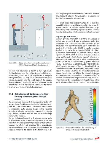
Due to fundamental research and a comprehensive analy- 156
sis of literature, a tool is now available, which allows a 3D 93.8
simulation of widespread earth-termination systems and also 1 m 31.3
considers the effect of soil ionisation. This is a considerable 0
improvement compared to the previous simplified analytic ap- Figure 5.7.2.1 HUGO model with feet in step position acting as
proaches. Moreover, the reaction of the human body to the contact points (source: TU Darmstadt)
160 LIGHTNING PROTECTION GUIDE www.dehn-international.com