
Page 162 - 35_DS702_E_2014_Lightning_Protection_Guide
P. 162
Source U k Calculations are performed in the stationary flow field. The
lightning current amplitude is assumed to be 100 kA.
IEC 60479-1 and IEC 60479-2 25 kV The soil was simulated by means of two different models:
Neuhaus 15 kV ¨ Model 1: The electrical properties of the soil are independ-
Dalziel 32 kV ent from other electrical parameters (“linear“). Unless
specified otherwise, an electrical conductivity of 0.001 S/m
Electric shock simulation (HUGO) 26.6 kV
is selected which corresponds to a resistivity of 1000 Ωm.
Table 5.7.2.1 Step / body voltage limit values according to different This represents a soil with a relatively poor electrical con-
sources ductivity.
¨ Model 2: Soil that changes its electrical conductivity de-
pending on the electric field strength (“non-linear“). This
model was selected to simulate the effect of soil ionisa-
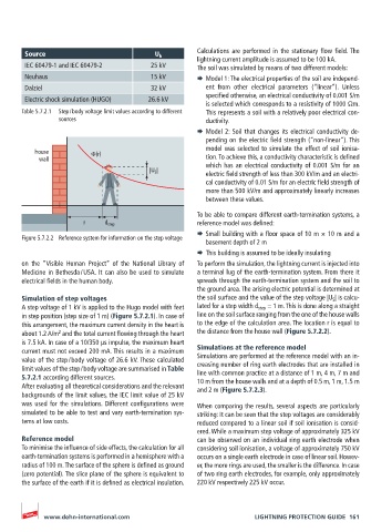
house Φ(r)
wall tion. To achieve this, a conductivity characteristic is defined
which has an electrical conductivity of 0.001 S/m for an
|U S |
electric field strength of less than 300 kV/m and an electri-
cal conductivity of 0.01 S/m for an electric field strength of
more than 500 kV/m and approximately linearly increases
between these values.
To be able to compare different earth-termination systems, a
r d step reference model was defined:
¨ Small building with a floor space of 10 m × 10 m and a
Figure 5.7.2.2 Reference system for information on the step voltage
basement depth of 2 m
¨ This building is assumed to be ideally insulating
on the “Visible Human Project” of the National Library of To perform the simulation, the lightning current is injected into
Medicine in Bethesda / USA. It can also be used to simulate a terminal lug of the earth-termination system. From there it
electrical fields in the human body. spreads through the earth-termination system and the soil to
the ground area. The arising electric potential is determined at
Simulation of step voltages the soil surface and the value of the step voltage |U S | is calcu-
A step voltage of 1 kV is applied to the Hugo model with feet lated for a step width d step = 1 m. This is done along a straight
in step position (step size of 1 m) (Figure 5.7.2.1). In case of line on the soil surface ranging from the one of the house walls
this arrangement, the maximum current density in the heart is to the edge of the calculation area. The location r is equal to
about 1.2 A/m and the total current flowing through the heart the distance from the house wall (Figure 5.7.2.2).
2
is 7.5 kA. In case of a 10/350 µs impulse, the maximum heart
current must not exceed 200 mA. This results in a maximum Simulations at the reference model
value of the step / body voltage of 26.6 kV. These calculated Simulations are performed at the reference model with an in-
creasing number of ring earth electrodes that are installed in
limit values of the step / body voltage are summarised in Table line with common practice at a distance of 1 m, 4 m, 7 m and
5.7.2.1 according different sources. 10 m from the house walls and at a depth of 0.5 m, 1 m, 1.5 m
After evaluating all theoretical considerations and the relevant and 2 m (Figure 5.7.2.3).
backgrounds of the limit values, the IEC limit value of 25 kV
was used for the simulations. Different configurations were When comparing the results, several aspects are particularly
simulated to be able to test and vary earth-termination sys- striking: It can be seen that the step voltages are considerably
tems at low costs. reduced compared to a linear soil if soil ionisation is consid-
ered. While a maximum step voltage of approximately 325 kV
Reference model can be observed on an individual ring earth electrode when
To minimise the influence of side effects, the calculation for all considering soil ionisation, a voltage of approximately 750 kV
earth-termination systems is performed in a hemisphere with a occurs on a single earth electrode in case of linear soil. Howev-
radius of 100 m. The surface of the sphere is defined as ground er, the more rings are used, the smaller is the difference. In case
(zero potential). The slice plane of the sphere is equivalent to of two ring earth electrodes, for example, only approximately
the surface of the earth if it is defined as electrical insulation. 220 kV respectively 225 kV occur.
www.dehn-international.com LIGHTNING PROTECTION GUIDE 161