
Page 163 - 35_DS702_E_2014_Lightning_Protection_Guide
P. 163
U S in kV U S in kV
800 350
700 1 ring 300 1 ring
600 2 rings 250 2 rings
3 rings 3 rings
500 4 rings 200 4 rings
400 Limit value Limit value
150
300
100
200
100 50
0 0
0 2 4 6 8 10 12 14 16 18 20 0 2 4 6 8 10 12 14 16 18 20
r in m r in m
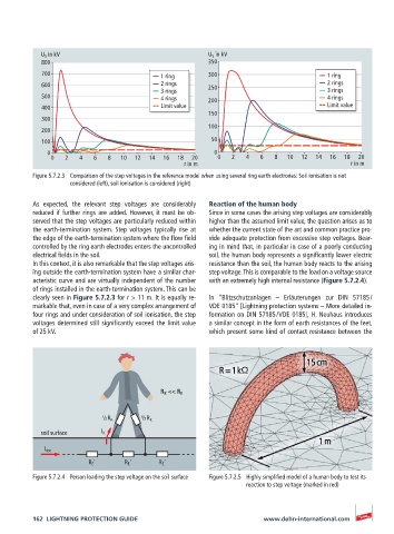
Figure 5.7.2.3 Comparison of the step voltages in the reference model when using several ring earth electrodes: Soil ionisation is not
considered (left), soil ionisation is considered (right)
As expected, the relevant step voltages are considerably Reaction of the human body
reduced if further rings are added. However, it must be ob- Since in some cases the arising step voltages are considerably
served that the step voltages are particularly reduced within higher than the assumed limit value, the question arises as to
the earth-termination system. Step voltages typically rise at whether the current state of the art and common practice pro-
the edge of the earth-termination system where the flow field vide adequate protection from excessive step voltages. Bear-
controlled by the ring earth electrodes enters the uncontrolled ing in mind that, in particular in case of a poorly conducting
electrical fields in the soil. soil, the human body represents a significantly lower electric
In this context, it is also remarkable that the step voltages aris- resistance than the soil, the human body reacts to the arising
ing outside the earth-termination system have a similar char- step voltage. This is comparable to the load on a voltage source
acteristic curve and are virtually independent of the number with an extremely high internal resistance (Figure 5.7.2.4).
of rings installed in the earth-termination system. This can be
clearly seen in Figure 5.7.2.3 for r > 11 m. It is equally re- In “Blitzschutzanlagen – Erläuterungen zur DIN 57185 /
markable that, even in case of a very complex arrangement of VDE 0185” [Lightning protection systems – More detailed in-
four rings and under consideration of soil ionisation, the step formation on DIN 57185 / VDE 0185], H. Neuhaus introduces
voltages determined still significantly exceed the limit value a similar concept in the form of earth resistances of the feet,
of 25 kV. which present some kind of contact resistance between the
R K << R E
½ R K ½ R K
soil surface I K
I tot
R E ‘ R E ‘ R E ‘
Figure 5.7.2.4 Person loading the step voltage on the soil surface Figure 5.7.2.5 Highly simplified model of a human body to test its
reaction to step voltage (marked in red)
162 LIGHTNING PROTECTION GUIDE www.dehn-international.com