
Page 164 - 35_DS702_E_2014_Lightning_Protection_Guide
P. 164
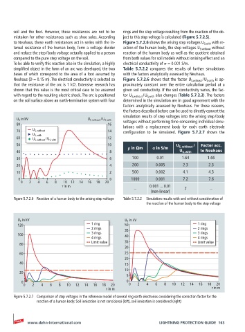
soil  and  the  feet.  However,  these  resistances  are  not  to  be   rings and the step voltage resulting from the reaction of the ob-
       mistaken for other resistances such as shoe soles. According   ject to this step voltage is calculated (Figure 5.7.2.5).
       to Neuhaus, these earth resistances act in series with the in-  Figure 5.7.2.6 shows the arising step voltages U S,with  with re-
       ternal resistance of the human body, form a voltage divider   action of the human body, the step voltages U S,without  without
       and reduce the step / body voltage actually applied to a person   reaction of the human body as well as the quotient obtained
       compared to the pure step voltage on the soil.  from both values for soil models without ionising effect and an
       To be able to verify this reaction also in the simulation, a highly   electrical conductivity of σ = 0.001 S/m.
       simplified object in the form of an arc was developed, the two   Table 5.7.2.2 compares the results of further simulations
       bases of which correspond to the area of a foot assumed by   with the factors analytically assessed by Neuhaus.
       Neuhaus (D = 0.15 m). The electrical conductivity is selected so   Figure 5.7.2.6 shows that the factor U S,without  / U S,with  is ap-
       that the resistance of the arc is 1 kΩ. Extensive research has   proximately constant over the entire calculation period at a
       shown that this value is the most critical case to be assumed   given soil conductivity. If the soil conductivity varies, the fac-
       with regard to the resulting electric shock. The arc is positioned   tor U S,without  / U S,with  also changes (Table 5.7.2.2). The factors
       on the soil surface above an earth-termination system with four   determined in the simulation are in good agreement with the
                                                    factors analytically assessed by Neuhaus. For these reasons,
                                                    the factors described before can be used to directly convert the
                                                    simulation results of step voltages into the arising step / body
        U S  in kV                    U S, without  /   U S, with  voltages without performing time-consuming individual simu-
        80                                    16
                                                    lations with a replacement  body for each earth electrode
        70     U S, without                   14    configuration  to  be  simulated.  Figure 5.7.2.7 shows the
               U S, with
        60     U S, without  /   U S, with    12
        50                                    10                          U S, without  /   Factor acc.
                                                      ρ in Ωm    σ in S/m
        40                                     8                            U S, with  to Neuhaus
        30                                     6        100       0.01       1.64      1.66
        20                                     4        200       0.005      2.3        2.3
        10                                     2        500       0,002      4.1        4.3
         0                                     0        1000      0.001      7.2        7.6
          0  2   4  6   8  10 12  14  16  18  20
                           r in m                              0.001 ... 0.01
                                                         –                    7         –
                                                                (non-linear)
       Figure 5.7.2.6  Reaction of a human body to the arising step voltage  Table 5.7.2.2  Simulation results with and without consideration of
                                                              the reaction of the human body to the step voltage


        U S  in kV                                   U S  in kV
        120                            1 ring        50                            1 ring
                                       2 rings       35                            2 rings
        100                            3 rings       40                            3 rings
                                       4 rings                                     4 rings
                                       Limit value   35                            Limit value
         80
                                                     30
         60                                          25
                                                     20
         40                                          15
                                                     10
         20
                                                      5
          0                                           0
           0  2   4   6   8  10  12  14  16  18  20    0  2   4   6  8   10  12  14  16  18  20
                                             r in m                                      r in m
       Figure 5.7.2.7  Comparison of step voltages in the reference model of several ring earth electrodes considering the correction factor for the
                reaction of a human body: Soil ionisation is not considered (left), soil ionisation is considered (right)


            www.dehn-international.com                             LIGHTNING PROTECTION GUIDE  163