
Page 165 - 35_DS702_E_2014_Lightning_Protection_Guide
P. 165
converted step voltage values for different earth electrode riod of 16 hours. After that, the humid sulphurous atmosphere
configurations. This shows that in case of an earth-termination is replaced.
system with three or four ring earth electrodes, the permissible Both components for outdoor use and components buried in
step voltages inside and outside the system are complied with. the ground must be subjected to ageing / conditioning. How-
It can be seen that common earth electrode configurations ever, additional requirements and measures must be con-
do not exceed the permissible step voltages based on the as- sidered for components buried in the ground. In general, no
sumptions described before. In general, it should be observed aluminium clamps or conductors should be installed in the
that significantly higher step voltages occur at the edge of ground. If stainless steel clamps or conductors are installed
every earth-termination system than within the earth elec- in the ground, only high-alloy stainless steel may be used,
trode region. e.g. StSt (V4A). In accordance with the German DIN VDE 0151
Further examinations are supposed to show up possibilities standard, StSt (V2A) is not permissible. Components for indoor
to optimise the design and installation of earth-termination use such as equipotential bonding bars do not have to be
systems. Moreover, it must be clarified whether stationary cal- subjected to ageing / conditioning. The same applies to compo-
culations correctly reflect the actual conditions and which ad- nents which are embedded in concrete. These components are
ditional effects occur in case of transient calculations. therefore often made of non-galvanised (black) steel.
5.8 Manufacturer’s test of lightning
protection components
Prior to a manufacturer’s test, metal lightning protection com-
ponents such as clamps, conductors, air-termination rods or
earth electrodes, which are exposed to all weather conditions,
must be subjected to artificial ageing / conditioning to prove
their suitability for this field of application.
Natural weathering and corrosion
According to IEC 60068-2-52 (EN 60068-2-52) and ISO 6988
(EN ISO 6988), artificial ageing and testing of metal compo-
nents is done in two steps.
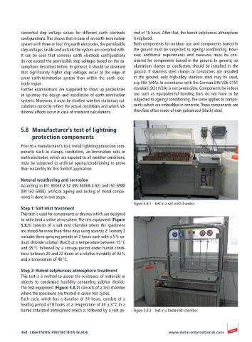
Figure 5.8.1 Test in a salt mist chamber
Step 1: Salt mist treatment
This test is used for components or devices which are designed
to withstand a saline atmosphere. The test equipment (Figure
5.8.1) consists of a salt mist chamber where the specimens
are tested for more than three days using severity 2. Severity 2
includes three spraying periods of 2 hours each with a 5 % so-
dium chloride solution (NaCl) at a temperature between 15 °C
and 35 °C followed by a storage period under humid condi-
tions between 20 and 22 hours at a relative humidity of 93 %
and a temperature of 40 °C.
Step 2: Humid sulphurous atmosphere treatment
This test is a method to assess the resistance of materials or
objects to condensed humidity containing sulphur dioxide.
The test equipment (Figure 5.8.2) consists of a test chamber
where the specimens are treated in seven test cycles.
Each cycle, which has a duration of 24 hours, consists of a
heating period of 8 hours at a temperature of 40 ± 3 °C in a
humid saturated atmosphere which is followed by a rest pe- Figure 5.8.2 Test in a Kesternich chamber
164 LIGHTNING PROTECTION GUIDE www.dehn-international.com