
Page 167 - 35_DS702_E_2014_Lightning_Protection_Guide
P. 167
with IEC 62561-1 (EN 62561-1) must be carried out for all
clamps.
The test procedure is described below based on the exam-
ple of a MV clamp. At first, it must be determined how many
combinations are to be tested. The MV clamp used is made of
stainless steel (V4A) and hence can be combined with steel,
aluminium, stainless steel (V4A) and copper conductors. More-
over, it can be connected in cross and parallel arrangement
which also has to be tested. This means that there are eight
possible test combinations for the MV clamp used (Figures
5.8.3 and 5.8.4).
In accordance with IEC 62561-1 (EN 62561-1), each of these
test combinations must be tested with three suitable speci-
mens / test set-ups. This means that 24 specimens of this single
MV clamp must be tested to cover the complete range. Every
single specimen is mounted with the adequate tightening
torque in compliance with normative requirements and is sub-
jected to artificial ageing consisting of a salt mist and humid
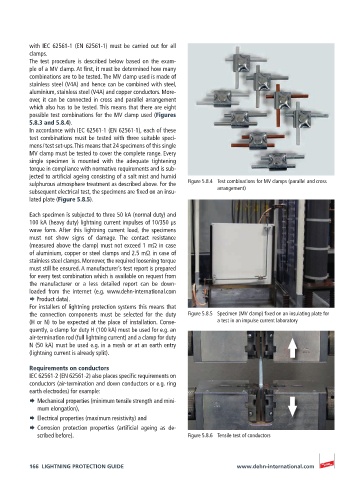
sulphurous atmosphere treatment as described above. For the Figure 5.8.4 Test combinations for MV clamps (parallel and cross
subsequent electrical test, the specimens are fixed on an insu- arrangement)
lated plate (Figure 5.8.5).
Each specimen is subjected to three 50 kA (normal duty) and
100 kA (heavy duty) lightning current impulses of 10/350 µs
wave form. After this lightning current load, the specimens
must not show signs of damage. The contact resistance
(measured above the clamp) must not exceed 1 mΩ in case
of aluminium, copper or steel clamps and 2.5 mΩ in case of
stainless steel clamps. Moreover, the required loosening torque
must still be ensured. A manufacturer’s test report is prepared
for every test combination which is available on request from
the manufacturer or a less detailed report can be down-
loaded from the internet (e.g. www.dehn-international.com
¨ Product data).
For installers of lightning protection systems this means that
the connection components must be selected for the duty Figure 5.8.5 Specimen (MV clamp) fixed on an insulating plate for
(H or N) to be expected at the place of installation. Conse- a test in an impulse current laboratory
quently, a clamp for duty H (100 kA) must be used for e.g. an
air-termination rod (full lightning current) and a clamp for duty
N (50 kA) must be used e.g. in a mesh or at an earth entry
(lightning current is already split).
Requirements on conductors
IEC 62561-2 (EN 62561-2) also places specific requirements on
conductors (air-termination and down conductors or e.g. ring
earth electrodes) for example:
¨ Mechanical properties (minimum tensile strength and mini-
mum elongation),
¨ Electrical properties (maximum resistivity) and
¨ Corrosion protection properties (artificial ageing as de-
scribed before). Figure 5.8.6 Tensile test of conductors
166 LIGHTNING PROTECTION GUIDE www.dehn-international.com