
Page 203 - 35_DS702_E_2014_Lightning_Protection_Guide
P. 203
tial bonding bar to the fixed earthing terminal and the connec- LPZ 1) must be integrated in the equipotential bonding system.
tion of pipes to the equipotential bonding system. While the equipotential bonding for data lines is described in
The integration of cable shields in the equipotential bonding section 7.5.3, the equipotential bonding for electrical power
system is described in chapter 7.3. lines will be described in the this section. The boundaries for the
equipotential bonding system at the transition from LPZ 0 A to
LPZ 1 are defined with the help of the specific design of the ob-
7.5.2 Equipotential bonding for power supply ject requiring protection. For installations supplied by low-volt-
systems age systems, the boundary LPZ 0 A / LPZ 1 is mostly assumed to
be the boundary of the building (Figure 7.5.2.1).
As is the case with metal installations, all electrical power
and data lines entering the building (transition from LPZ 0 A to
SPD SPD
0/1 0/1
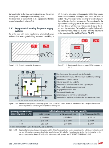
Figure 7.5.2.1 Transformer outside the structure Figure 7.5.2.2 Transformer inside the structure (LPZ 0 integrated in
LPZ 1)
Reinforcement of the outer walls and the foundation
Other earth electrodes, e.g. intermeshing to neighbouring buildings
Connection to the reinforcement
Internal (potential) ring conductor
Connection to external conductive parts, e.g. water pipe
Type B earth electrode, ring earth electrode
Surge protective device (SPD)
Equipotential bonding bar
Electrical power or information technology line
Connection to additional earth electrodes, type A earth electrodes
Figure 7.5.2.3 Example of an equipotential bonding system in a structure with several entries for the external conductive parts and with an
inner ring conductor connecting the equipotential bonding bars
Lightning protection level Lightning impulse current carrying capability
(previously: class of LPS) In TN systems In TN systems (L – N) In TT systems (N – PE)
I ≥ 100 kA/m ≥ 100 kA/m ≥ 100 kA
II ≥ 75 kA/m ≥ 75 kA/m ≥ 75 kA
III / IV ≥ 50 kA/m ≥ 50 kA/m ≥ 50 kA
m: number of conductors, e.g. m = 5 in case of L1, L2, L3, N and PE
Table 7.5.2.1 Required lightning impulse current carrying capability of type 1 surge protective devices depending on the lightning protection level and
the type of low-voltage consumer’s installation (see also German VDN guideline “Surge Protective Devices Type 1 – Guideline for the
use of surge protective devices (SPDs) Type 1 in main power supply systems” and IEC 60364-5-53 (HD 60364-5-534))
202 LIGHTNING PROTECTION GUIDE www.dehn-international.com