
Page 201 - 35_DS702_E_2014_Lightning_Protection_Guide
P. 201
¨ Ventilation ducts
¨ Lift rails
¨ Metal floors
¨ Supply lines
A grid structure of the equipotential bonding network of
around 5 m x 5 m would be ideal. This typically reduces the
electromagnetic lightning field inside an LPZ by a factor of 2
(corresponding to 6 dB).
Enclosures and racks of electronic devices and systems should
be integrated in the equipotential bonding network by means Figure 7.4.3 Connection of the ring equipotential bonding bar to
of short connections. To this end, a sufficient number of equi- the equipotential bonding network via a fixed earthing
potential bonding bars and / or ring equipotential bonding terminal
bars (Figure 7.4.2) must be provided in the structure. These
bars must be connected to the equipotential bonding network
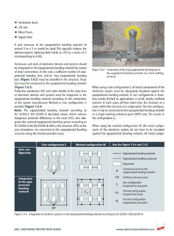
(Figure 7.4.3). When using a star configuration S, all metal components of the
Protective conductors (PE) and cable shields of the data lines electronic system must be adequately insulated against the
of electronic devices and systems must be integrated in the equipotential bonding network. A star configuration is there-
equipotential bonding network according to the instructions fore mostly limited to applications in small, locally confined
of the system manufacturer. Meshed or star configuration is systems. In such cases, all lines must enter the structure or a
possible (Figure 7.4.4). room within the structure at a single point. The star configura-
Note: The equipotential bonding network according to tion S may be connected to the equipotential bonding network
IEC 62305-4 (EN 62305-4) described above, which reduces at a single earthing reference point (ERP) only. This results in
dangerous potential differences in the inner LPZs, also inte- the configuration S S .
grates the meshed equipotential bonding system according to
IEC 60364-4-44 (HD 60364-4-444) in the structure. SPDs at the When using the meshed configuration M, the metal compo-
zone boundaries are connected to this equipotential bonding nents of the electronic system do not have to be insulated
structure along the shortest possible route. against the equipotential bonding network. All metal compo-
Star configuration S Meshed configuration M Key for Figure 7.4.4 and 7.4.5
Basic con-
figuration Equipotential bonding network
Equipotential bonding conductor
S M
Equipment
Connection point to the
equipotential bonding network
Integration ERP Earthing reference point
in the equi- Star configuration
potential S s integrated by star point
bonding
network S s M m Meshed configuration
M m
integrated by mesh
Meshed configuration
M s
integrated by star point
ERP
Figure 7.4.4 Integration of electronic systems in the equipotential bonding network according to IEC 62305-4 (EN 62305-4)
200 LIGHTNING PROTECTION GUIDE www.dehn-international.com