
Page 200 - 35_DS702_E_2014_Lightning_Protection_Guide
P. 200
Low-impedance shield earthing LPZs. This applies to interferences to be expected from the sur-
Cable shields can conduct impulse currents of up to several kA. roundings of the shielded cable (e.g. electromagnetic fields)
During the discharge, the impulse currents flow through the and for meshed equipotential bonding conforming to the
shield and the shield terminal to earth. The impedance of the standard. However, it must be observed that hazards can still
cable shield and the shield terminal create voltage differences arise depending on the installation conditions and arresters
between the shield potential and earth. In such a case, volt- may be required. Typical potential hazards are: the supply of
ages of up to some kV can develop and destroy the insulation terminal devices from different main low-voltage distribution
of conductors or connected devices. Coarse-meshed shields boards, TN-C systems, high transfer impedances of the cable
and twisting of the cable shield (pig tail) for connection in a shields or insufficient earthing of the shield. Caution must be
terminal block are particularly critical. The quality of the cable exercised in case of cables with poorly covered shields, which
shield used affects the number of shield earthings required. are often used for economic reasons. This leads to residual
Under certain circumstances, earthing is required every 10 me- interferences on the signal cores. Such interferences can be
tres in order to achieve a sufficient shielding effect. Suitable controlled by using a high-quality shielded cable or surge pro-
large-area contact terminals with slipping spring elements are tective devices.
recommended for shield connection. This is important to com-
pensate the yield of the plastic insulation of the conductors
(Figure 7.3.1.5). 7.4 Equipotential bonding network
Maximum length of shielded cables The main function of the equipotential bonding network is to
Cable shields have a so-called transfer impedance, which prevent hazardous potential differences between all devices /
roughly corresponds to the d.c. resistance specified by the installations in the inner LPZs and to reduce the magnetic field
cable manufacturer. An interference impulse flowing through of the lightning strike. The low-inductance equipotential bond-
the resistance creates a voltage drop on the cable shield. The ing network required is achieved by multiply interconnecting
permissible transfer impedance for the cable shield can be de- all metal components by means of equipotential bonding con-
termined depending on the dielectric strength of the terminal ductors inside the LPZ of the structure. This creates a three-
device and the cable as well as the cable length. It is crucial dimensional meshed network (Figure 7.4.1). Typical compo-
that the voltage drop is lower than the insulation strength of nents of the network are:
the system (Figure 7.3.1.6). If this is not the case, arresters ¨ All metal installations (e.g. pipes, boilers)
must be used.
¨ Reinforcements in the concrete (in floors, walls and ceil-
ings)
Extension of LPZs with the help of shielded cables
According to IEC 62305-4 (EN 62305-4), no arresters have to ¨ Gratings (e.g. intermediate floors)
be installed if a shielded cable is used between two identical ¨ Cable ducts
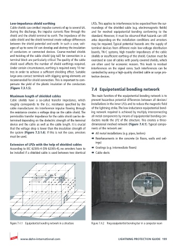
Figure 7.4.1 Equipotential bonding network in a structure Figure 7.4.2 Ring equipotential bonding bar in a computer room
www.dehn-international.com LIGHTNING PROTECTION GUIDE 199