
Page 205 - 35_DS702_E_2014_Lightning_Protection_Guide
P. 205
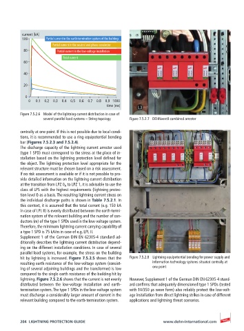
current [kA]
          100       Partial current in the earth-termination system of the building
                       Partial current in the neutral and phase conductor
           80            Partial current in the low-voltage installation
                           Total current
           60

           40

           20

            0
             0  0.1  0.2  0.3  0.4  0.5  0.6  0.7  0.8  0.9 1000
                                              time [ms]
          Figure 7.5.2.6  Model of the lightning current distribution in case of
                   several parallel load systems – String topology  Figure 7.5.2.7  DEHNventil combined arrester


          centrally at one point. If this is not possible due to local condi-
          tions, it is recommended to use a ring equipotential bonding
          bar (Figures 7.5.2.3 and 7.5.2.4).
          The discharge capacity of the lightning current arrester used
          (type 1 SPD) must correspond to the stress at the place of in-
          stallation based on the lightning protection level defined for
          the object. The lightning protection level appropriate for the
          relevant structure must be chosen based on a risk assessment.
          If no risk assessment is available or if it is not possible to pro-
          vide detailed information on the lightning current distribution
          at the transition from LPZ 0 A  to LPZ 1, it is advisable to use the
          class of LPS with the highest requirements (lightning protec-
          tion level I) as a basis. The resulting lightning current stress on
          the individual discharge paths is shown in Table 7.5.2.1. In
          this context, it is assumed that the total current (e.g. 150 kA
          in case of LPL II) is evenly distributed between the earth-termi-
          nation system of the relevant building and the number of con-
          ductors (m) of the type 1 SPDs used in the low-voltage system.
          Therefore, the minimum lightning current carrying capability of
          a type 1 SPD is 75 kA/m in case of e.g. LPL II.
          Supplement 1 of the German DIN EN 62305-4 standard ad-
          ditionally describes the lightning current distribution depend-
          ing on the different installation conditions. In case of several
          parallel load systems, for example, the stress on the building
          hit by lightning is increased. Figure 7.5.2.5 shows that the   Figure 7.5.2.8  Lightning equipotential bonding for power supply and
          resulting earth resistance of the low-voltage system (consist-  information technology systems situated centrally at
          ing of several adjoining buildings and the transformer) is low   one point
          compared to the single earth resistance of the building hit by
          lightning. Figure 7.5.2.6 shows that the current is not evenly   However, Supplement 1 of the German DIN EN 62305-4 stand-
          distributed between the low-voltage installation and earth-  ard confirms that adequately dimensioned type 1 SPDs (tested
          termination system. The type 1 SPDs in the low-voltage system   with 10/350 µs wave form) also reliably protect the low-volt-
          must discharge a considerably larger amount of current in the   age installation from direct lightning strikes in case of different
          relevant building compared to the earth-termination system.  applications and lightning threat scenarios.


          204  LIGHTNING PROTECTION GUIDE                            www.dehn-international.com