
Page 199 - 35_DS702_E_2014_Lightning_Protection_Guide
P. 199
metres between buildings. Especially with older installations, it
can happen that one part of the earth-termination systems is
no longer in operation or that no meshed equipotential bond-
ing network is installed. In such cases, interferences can occur
as a result of multiple shield earthing. Potential differences of
the different earth-termination systems of the building can
allow low-frequency equalising currents (n x 50 Hz) and the
transients superimposed thereon to flow. At the same time,
currents measuring up to a few amperes are possible which, in
extreme cases, can cause cable fires. In addition, crosstalk can
direct earthing
cause signal interference if the signal frequency is in a similar
MEB 1 indirect earth- MEB 2 frequency range to the interference signal.
ing via gas
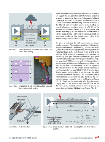
discharge tube The aim is to implement the EMC requirements and prevent
MEB 1 ≠ MEB 2 equalising currents. This can be achieved by combining direct
single-ended and indirect shield earthing. All shields are direct-
Figure 7.3.1.3 Shield connection at both ends – Solution: Direct and ly connected with the local equipotential bonding system at a
indirect shield earthing central point such as the control room. At the far ends of the
cable, the shields are indirectly connected to the earth potential
via isolating spark gaps. Since the resistance of a spark gap is
around 10 GΩ, equalising currents are prevented during surge-
free operation. If EMC interference such as lightning strikes oc-
1 1´
curs, the spark gap ignites and discharges the interference im-
2 2´ pulse without destruction. This reduces the residual impulse on
the active cable cores and the terminal devices are subject to
protected even less stress. The two-pole BLITZDUCTOR XT arrester allows
direct or indirect shield earthing. A gas discharge tube, which
3 3´
eliminates interference impulses via the cable shield, can be
installed at one side between the cable shield and the equi-
4 4´
potential bonding system for indirect shield earthing (Figure
7.3.1.3). Thanks to the combination of a lightning current
carrying SAK BXT LR shield terminal and BLITZDUCTOR XT,
Figure 7.3.1.4 BLITZDUCTOR XT with SAK BXT LR shield terminal with the coding at the terminal connection allows to change be-
direct or indirect shield earthing tween direct and indirect shield earthing (Figure 7.3.1.4).
shield terminal
I = 5 kA
cable shield
l = 200 m
insulation strength U ISO = 2 kV
cable U 2000V
Requested: Maximum R Kh I iso 5000A 0.4
permissible transfer
anchor bar 0.4 10 3
impedance R Kh l = 200 m R 2
of the cable shield Kh 200m m
Figure 7.3.1.5 Shield connection Figure 7.3.1.6 Shield connection at both ends – Shielding from capacitive / inductive
coupling
198 LIGHTNING PROTECTION GUIDE www.dehn-international.com