
Page 202 - 35_DS702_E_2014_Lightning_Protection_Guide
P. 202
possible to the points where the lines and metal installations
combination 1 combination 2
enter the structure. The lines should be kept as short as pos-
sible (low impedance).
The minimum cross-sections listed in Table 7.5.1 for connect-
ing the equipotential bonding bar to the earth-termination
system, interconnecting the different equipotential bonding
S s M s
bars and connecting the metal installations to the equipoten-
tial bonding bar must be taken into account for equipotential
bonding.
ERP ERP
The following metal installations must be incorporated into
the equipotential bonding system:
M m M m ¨ Metal cable ducts
¨ Shielded cables and lines
¨ Building reinforcement
¨ Metal water supply pipes
Figure 7.4.5 Combination of the integration methods according to ¨ Metal conduits for lines
Figure 7.4.4: Integration in the equipotential bonding
network according to IEC 62305-4 (EN 62305-4) ¨ Other metal pipe systems or conductive parts (e.g. com-
pressed air)
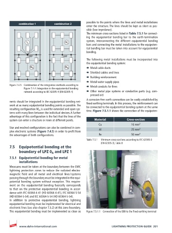
A corrosion-free earth connection can be easily established by
nents should be integrated in the equipotential bonding net- fixed earthing terminals. In this process, the reinforcement can
work at as many equipotential bonding points as possible. The be connected to the equipotential bonding system at the same
resulting configuration M m is used for extended and open sys- time. Figure 7.5.1.1 shows the connection of the equipoten-
tems with many lines between the individual devices. A further
advantage of this configuration is the fact that the lines of the
system can enter a structure or room at different points. Material Cross-section
Cu 16 mm 2
Star and meshed configurations can also be combined in com- 2
plex electronic systems (Figure 7.4.5) in order to profit from Al 25 mm
the advantages of both configurations. Fe 50 mm 2
Table 7.5.1 Minimum cross-sections according to IEC 62305-3
(EN 62305-3), Table 8
7.5 Equipotential bonding at the
boundary of LPZ 0 and LPZ 1
A
7.5.1 Equipotential bonding for metal
installations
Measures must be taken at the boundary between the EMC
lightning protection zones to reduce the radiated electro-
magnetic field and all metal and electrical lines / systems
passing through the boundary must be integrated in the equi-
potential bonding system without exception. This require-
ment on the equipotential bonding basically corresponds
to that on the protective equipotential bonding in accor-
dance with IEC 60364-4-41 (HD 60364-4-41), IEC 60364-5-54
(HD 60364-5-54) and IEC 60364-5-54 (HD 60364-5-54).
In addition to protective equipotential bonding, lightning
equipotential bonding must be implemented for electrical and
electronic lines (see also chapter 7.5.2) at this zone boundary.
This equipotential bonding must be implemented as close as Figure 7.5.1.1 Connection of the EBB to the fixed earthing terminal
www.dehn-international.com LIGHTNING PROTECTION GUIDE 201