
Page 204 - 35_DS702_E_2014_Lightning_Protection_Guide
P. 204
For objects which are directly supplied by the medium-voltage Additional shielding measures for the incoming medium-volt-
system, LPZ 0 A is extended up to the secondary side of the age line prevent partial lightning currents in LPZ 0 from flow-
transformer. Lightning equipotential bonding is implemented ing into parts of the installation / systems in LPZ 1.
on the 230/400 V side of the transformer (Figure 7.5.2.2). To prevent equalising currents between the various equipo-
To avoid damage to the transformer, it is recommended to ad- tential bonding points in an electrical installation, it is rec-
ditionally use surge protective devices on the high-voltage side ommended to implement lightning equipotential bonding of
of the transformer. all incoming metal lines and electrical power and data lines
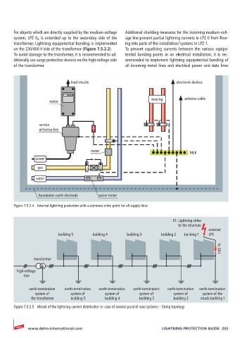
load circuits electronic devices
heating antenna cable
meter
service
entrance box
meter MEB
power
gas
water
foundation earth electrode water meter
Figure 7.5.2.4 Internal lightning protection with a common entry point for all supply lines
S1: Lightning strike
to the structure
external
building 5 building 4 building 3 building 2 building 1 LPS
100 %
transformer
high-voltage
line
earth-termination earth-termination earth-termination earth-termination earth-termination earth-termination
system of system of system of system of system of system of the
the transformer building 5 building 4 building 3 building 2 struck building 1
Figure 7.5.2.5 Model of the lightning current distribution in case of several parallel load systems – String topology
www.dehn-international.com LIGHTNING PROTECTION GUIDE 203