
Page 198 - 35_DS702_E_2014_Lightning_Protection_Guide
P. 198
C
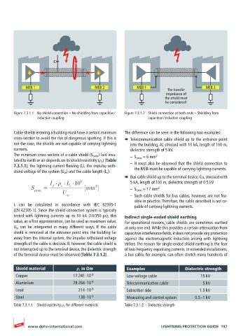
MEB 1 MEB 2 MEB 1 MEB 2
The transfer
impedance of
the shield must
be considered!
Figure 7.3.1.1 No shield connection – No shielding from capacitive / Figure 7.3.1.2 Shield connection at both ends – Shielding from
inductive coupling capacitive / inductive coupling
Cable shields entering a building must have a certain minimum The difference can be seen in the following two examples:
cross-section to avoid the risk of dangerous sparking. If this is ¨ Telecommunication cable shield up to the entrance point
not the case, the shields are not capable of carrying lightning into the building, Al, stressed with 10 kA, length of 100 m,
currents. dielectric strength of 5 kV.
The minimum cross-section of a cable shield (S cmin ) laid insu- – S cmin ≈ 6 mm
2
lated to earth or air depends on its shield resistivity (ρ c ) (Table
7.3.1.1), the lightning current flowing (l f ), the impulse with- – It must also be observed that the shield connection to
stand voltage of the system (U w ) and the cable length (L c ): the MEB must be capable of carrying lightning currents.
¨ Bus cable shield up to the terminal device, Cu, stressed with
I L 10 6 5 kA, length of 100 m, dielectric strength of 0.5 kV
S = f c c [mm ] – S cmin ≈ 17 mm 2
2
cmin
U
w – Such cable shields for bus cables, however, are not fea-
sible in practice. Therefore, the cable described is not ca-
I f can be calculated in accordance with IEC 62305-1 pable of carrying lightning currents.
(EN 62305-1). Since the shield connection system is typically
tested with lightning currents up to 10 kA (10/350 μs), this Indirect single-ended shield earthing
value, as a first approximation, can be used as maximum value. For operational reasons, cable shields are sometimes earthed
U w can be interpreted in many different ways. If the cable at only one end. While this provides a certain attenuation from
shield is removed at the entrance point into the building far capacitive interference fields, it does not provide any protection
away from the internal system, the impulse withstand voltage against the electromagnetic induction arising with lightning
strength of the cable is decisive. If, however, the cable shield is strikes. The reason for single-ended shield earthing is the fear
not interrupted up to the terminal device, the dielectric strength of low-frequency equalising currents. In extended installations,
of the terminal device must be observed (Table 7.3.1.2). a bus cable, for example, can often stretch many hundreds of
Shield material ρ c in Ωm Examples Dielectric strength
Copper 17.241 ∙ 10 -9 Low-voltage cable 15 kV
Aluminium 28.264 ∙ 10 -9 Telecommunication cable 5 kV
Lead 214 ∙ 10 -9 Subscriber side 1.5 kV
Steel 138 ∙ 10 -9 Measuring and control system 0.5 – 1 kV
Table 7.3.1.1 Shield resistivity ρ c for different materials Table 7.3.1.2 Dielectric strength
www.dehn-international.com LIGHTNING PROTECTION GUIDE 197