
Page 229 - 35_DS702_E_2014_Lightning_Protection_Guide
P. 229
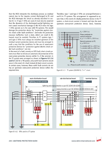
that the RCD interprets this discharge process as residual   Therefore, type 1 and type 2 SPDs are arranged between L
          current due to the impulse current discharged to PE and   and N in TT systems. This arrangement is supposed to en-
          the RCD interrupts the circuit as already described in sec-  sure that, in the event of a faulty protective device in the TT
          tion 8.1.3. If type 1 SPDs are used, it must also be assumed   system, a short-circuit current is formed and trips the next
          that the dynamics of the discharged partial lightning cur-  upstream overcurrent protective device. Since, however,
          rent causes mechanical damage to the RCD when the type
          1 SPDs operate as is the case with TN systems. This would
          damage the protective device for “protection against elec-
          tric shock under fault conditions” and make the protection   L1    U 0  = 230 V a.c.
          measure ineffective. Such a state, which can result in life   L2   Phase conductor to
                                                         L3
          hazard, must be avoided. Therefore, in TT systems type 1   N       neutral conductor:
          and type 2 SPDs must always be installed upstream of the   PE      U c  ≥ 1.1 x 230 V = 253 V a.c.
          residual current protective device and must be arranged in         Neutral conductor to PE:
          such a way that the conditions for the use of overcurrent   1.1 U 0  U c  ≥ 230 V a.c.
          protective devices for “protection against electric shock un-      3 x arrester with U c  ≥ 253 V a.c.
          der fault conditions” are met.                                     1 x arrester with U c  ≥ 230 V a.c.
          In the event of a fault, namely an SPD fault, short-circuit cur-  U 0  The values of U 0  between the
          rents must flow to initiate an automatic disconnection of the      neutral conductor and PE al-
          overcurrent protective devices within 5 s. If the arresters in     ready refer to the most un-
                                                                             favourable operating con-
          the TT system were arranged as shown in Figures 8.1.3.4            ditions. Therefore, a tolerance
          and 8.1.3.5 for a TN system, only earth fault currents would       of 10 % is not considered.
          occur in the event of a fault instead of short-circuit currents.   R A
          In certain cases, however, these earth fault currents do not   U 0  = Phase-to-earth nominal a.c. voltage
          trip an upstream overcurrent protective device within the
          required time.                               Figure 8.1.4.1  TT system (230/400 V); “3+1” circuit


                     external LPS  lightning current arrester  sub-distribution board  surge arrester terminal devices
                             main distribution board

                                          lightning and surge protection as per IEC 62305 (EN 62305)

                            F1                         surge protection as per IEC 60364-4-44 (HD 60364-4-443)
                                                                                            L1
                                                                                            L2
                                           Wh                               RCD             L3
                                                                                            N
                           SEB                                                              PE
                                         F2
                                                                        F3


                                        MEB                    local EBB


          Figure 8.1.4.2  SPDs used in a TT system


          228  LIGHTNING PROTECTION GUIDE                            www.dehn-international.com