
Page 230 - 35_DS702_E_2014_Lightning_Protection_Guide
P. 230
lightning currents always flow to earth, namely PE, an ad- II I imp ≥ 75 kA (10/350 μs)
ditional discharge path must be provided between N and PE. III / IV I imp ≥ 50 kA (10/350 μs)
These so-called “N-PE arresters” must meet special require-
ments since in this case the sum of the partial discharge The type 2 SPDs are also connected between L and N and be-
currents from L1, L2, L3 and N must be conducted and they tween N and PE. Type 2 SPDs between N and PE must have a
must be capable of extinguishing follow currents of 100 A rms discharge capacity of at least I n ≥ 20 kA (8/20 μs) for three-
due to a possible shifting of the neutral point. phase systems and I n ≥ 10 kA (8/20 μs) for a.c. systems.
Moreover, an N-PE arrester must fulfil increased TOV require- Since coordination is always based on the worst-case condi-
ments. According to IEC 60364-5-53 (HD 60364-5-534), a tions (10/350 μs wave form), type 2 N-PE arresters of the
withstand capability of 1200 V for 200 ms must be proven. Red/Line series have a value of 12 kA (10/350 μs).
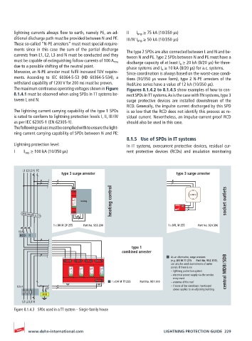
The maximum continuous operating voltages shown in Figure Figures 8.1.4.2 to 8.1.4.5 show examples of how to con-
8.1.4.1 must be observed when using SPDs in TT systems be- nect SPDs in TT systems. As is the case with TN systems, type 3
tween L and N. surge protective devices are installed downstream of the
RCD. Generally, the impulse current discharged by this SPD
The lightning current carrying capability of the type 1 SPDs is so low that the RCD does not identify this process as re-
is rated to conform to lightning protection levels I, II, III / IV sidual current. Nevertheless, an impulse-current-proof RCD
as per IEC 62305-1 (EN 62305-1). should also be used in this case.
The following values must be complied with to ensure the light-
ning current carrying capability of SPDs between N and PE:
8.1.5 Use of SPDs in IT systems
Lightning protection level: In IT systems, overcurrent protective devices, residual cur-
I I imp ≥ 100 kA (10/350 μs) rent protective devices (RCDs) and insulation monitoring
L1 L2 L3 NPE
type 3 surge arrester type 3 surge arrester
heating control socket outlets
1 2
heating
DEHNrail DR M 2P 255 FM DEHNflex
cable length ≥ 5 m
1 x DR M 2P 255 Part No. 953 200 1 x DFL M 255 Part No. 924 396
16 A
RCD
type 1
combined arrester
As an alternative, surge arresters
L1 L2 L3 N
(e.g. DG M TT 275 Part No. 952 310),
can also be used downstream of meter
panels if there is no
DEHNventil DV MOD 255 DEHNventil DV MOD 255 DEHNventil DV MOD 255 DEHNventil DV MOD NPE 50 – lightning protection system central MDB / SDB
– electrical power supply via the service
entry mast
1 x DV M TT 255 Part No. 951 310 – antenna of the roof
PE
125 A – if none of the conditions mentioned
above applies to an adjoining building
MEB
L1 L2 L3 N
Figure 8.1.4.3 SPDs used in a TT system – Single-family house
www.dehn-international.com LIGHTNING PROTECTION GUIDE 229