
Page 233 - 35_DS702_E_2014_Lightning_Protection_Guide
P. 233
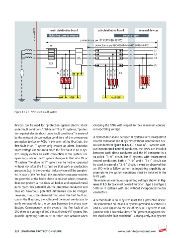
external LPS  lightning current arrester  protection as per IEC 62305 (EN 62305)  surge arrester terminal devices
                                                          sub-distribution board
                              main distribution board


                              F1                        protection as per IEC 60364-4-44 (HD 60364-4-443)
                                                                                          L1
                                                                                          L2
                                              Wh                                          L3

                              SEB
                                                                                          PE
                                  F2                                  F3


                                         MEB                     local EBB


          Figure 8.1.5.1  SPDs used in a IT system


          devices can be used for “protection against electric shock   choosing the SPDs with respect to their maximum continu-
          under fault conditions“. While in TN or TT systems, “protec-  ous operating voltage.
          tion against electric shock under fault conditions” is ensured
          by the relevant disconnection conditions of the overcurrent   A distinction is made between IT systems with incorporated
          protective devices or RCDs in the event of the first fault, the   neutral conductor and IT systems without incorporated neu-
          first fault in an IT system only creates an alarm. Excessive   tral conductor (Figure 8.1.5.1). In case of IT systems with-
          touch voltage cannot occur since the first fault in an IT sys-  out incorporated neutral conductor, the SPDs are installed
          tem simply creates an earth connection of the system. The   between each phase conductor and the PE conductor in a
          operating state of the IT system changes to that of a TN or   so-called “3 – 0” circuit. For IT systems with incorporated
          TT system. Therefore, an IT system can be further operated   neutral conductors, both a “4 – 0” and a “3+1” circuit can
          without risk after the first fault so that work or production   be used. In case of a “3+1” circuit, it must be observed that
                                                       an SPD with a follow current extinguishing capability ap-
          processes (e.g. in the chemical industry) can still be complet-  propriate to the system conditions must be installed in the
          ed. In case of the first fault, the protective conductor reaches   N-PE path.
          the potential of the faulty phase conductor, which, however,   The maximum continuous operating voltages shown in Fig-
          does not present a risk since all bodies and exposed metal   ures 8.1.5.1a to c must be used for type 1, type 2 and type 3
          parts reach this potential via the protective conductor and   SPDs in IT systems with and without incorporated neutral
          thus no hazardous potential differences can be bridged.   conductors.
          However, it must be observed that when the first fault oc-
          curs in the IT system, the voltage of the intact conductors to   A second fault in an IT system must trip a protective device.
          earth corresponds to the voltage between the phase con-  The information on TN and TT systems provided in section 8.1
          ductors. Consequently, in the event of the first fault of an   and 8.2 also applies to the use of SPDs in IT systems in con-
          SPD there is a voltage of 400 V in a 230/400 V IT system. This   junction with a protective device for "protection against elec-
          possible operating state must be taken into account when   tric shock under fault conditions". Consequently, in IT systems


          232  LIGHTNING PROTECTION GUIDE                            www.dehn-international.com