
Page 234 - 35_DS702_E_2014_Lightning_Protection_Guide
P. 234
L1 U L-L = 400 V a.c.
L2 L1 L2 L3 PE
L3 Phase conductor to PE: type 2 surge arrester
PE U c ≥ 1.1 x U L-L
≥ 1.1 x 400 V a.c. = 440 V a.c. 100 A
fault indication
1.1 U L-L
DEHNguard DEHNguard DEHNguard
DG 1000 FM DG 1000 FM DG 1000 FM
R A
Figure 8.1.5.2a IT system without incorporated neutral conductor;
“3 – 0” circuit
3 x DG 1000 FM Part No. 950 112
1 x EB DG 1000 1 3 Part No. 900 411
L1 U L-L = 400 V a.c.
L2 U 0 = 230 V a.c.
L3 Phase conductor to PE: coordinated type 1
N lightning current arrester
PE U c ≥ 1.1 x U L-L
≥ 1.1 x 400 V a.c. = 440 V a.c. 250 A
1.1 Neutral conductor to PE:
1.1 U L-L U 0
U c ≥ 1.1 x U 0 L L L
≥ 1.1 x 230 V a.c. = 253 V a.c.
3 x arrester with U c ≥ 440 V a.c.
1 x arrester with U c ≥ 253 V a.c.
R A DEHNbloc Maxi DBM 1 760 FM DEHNbloc Maxi DBM 1 760 FM DEHNbloc Maxi DBM 1 760 FM
U 0 = Phase-to-neutral nominal a.c. voltage
Figure 8.1.5.2b IT system with incorporated neutral conductor; N/PEN N/PEN N/PEN fault indication
“4 – 0” circuit
3 x DBM 1 760 FM Part No. 961 175
MEB 1 x EB DG 1000 1 3 Part No. 900 411
L1 U L-L = 400 V a.c.
L2 U 0 = 230 V a.c.
L3
N Phase conductor to neutral L1 L2 L3 PE
PE conductor:
U c ≥ 1.1 x U 0
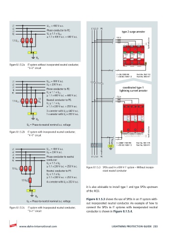
≥ 1.1 x 230 V a.c. = 253 V a.c. Figure 8.1.5.3 SPDs used in a 690 V IT system – Without incorpo-
1.1 U 0
Neutral conductor to PE: rated neutral conductor
U c ≥ 1.1 x U 0
≥ 1.1 x 230 V a.c. = 253 V a.c.
1.1 U 0
4 x arrester with U c ≥ 253 V a.c.
it is also advisable to install type 1 and type SPDs upstream
of the RCD.
R A
Figure 8.1.5.3 shows the use of SPDs in an IT system with-
U 0 = Phase-to-neutral nominal a.c. voltage
out incorporated neutral conductor. An example of how to
Figure 8.1.5.2c IT system with incorporated neutral conductor; connect the SPDs in IT systems with incorporated neutral
“3+1” circuit conductor is shown in Figure 8.1.5.4.
www.dehn-international.com LIGHTNING PROTECTION GUIDE 233