
Page 235 - 35_DS702_E_2014_Lightning_Protection_Guide
P. 235
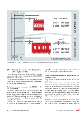
L1 L2 L3 N PE

                                                                                             sub-distribution board
                                                                   type 2 surge arrester
                                   125 A
                                                                  4 x DG S 275   Part No. 952 070
                                                                  1x DK 25   Part No. 952 699
                                           DEHNguard  DG MOD 275  DEHNguard  DG MOD 275  DEHNguard  DG MOD 275  Feed-Through  Terminal  DK 25  DEHNguard  DG MOD 275  1x MVS 1 4   Part No. 900 610
                                                                  1x MVS 1 2
                                                                           Part No. 900 617


                                                                        DEHNbloc ®
                                                                    coordinated type 1
                                        L/N  L’/N’  L/N  L’/N’  L/N  L’/N’  L/N  L’/N’
                                   315 A                         lightning current arrester

                                           DEHNbloc  DB H MOD   255  DEHNbloc  DB H MOD   255  DEHNbloc  DB H MOD   255  Feed-Through  Terminal  DK 25  DEHNbloc  DB H MOD   255  4x DB M 1 255  Part No. 961 120  main distribution board
                                                                  1x DK 25   Part No. 952 699
                                                                  1x MVS 1 6   Part No. 900 815
                                                                  1x MVS 1 2   Part No. 900 617
                                           N/PE(N)  N/PE(N)  N/PE(N)  N/PE(N)

                          MEB
                                                                 Only required, if no fuse of the same or a lower
                                                                 nominal value is provided in the upstream system.
          Figure 8.1.5.4  SPDs used in a 230/400 V IT system – With incorporated neutral conductor (3+1 circuit)


          8.1.6  Determination of the correct connecting   Figure 8.1.6.1. To this end, no separate cable branches are
               cable lengths for SPDs                  used for connecting the surge protective devices.
          The determination of the correct connecting cable lengths for
          surge protective devices is an integral part of the IEC 60364-5-53    Parallel connection in accordance with IEC 60364-5-53
          (HD 60364-5-534) standard.                   (HD 60364-5-534)
          The aspects described below are also frequent reasons for   The optimal series connection cannot be used for all system
          complaints by experts, members of technical inspectorates,   conditions.
          etc. who inspect the installation.           The nominal currents, which are conducted via the double
                                                       terminals on the surge protective device in case of series
          Series connection in accordance with IEC 60364-5-53   connection, are limited by the thermal withstand capability
          (HD 60364-5-534)                             of the double terminals. For this reason, the manufacturer of
          The impulse voltage level which is actually applied to the   the surge protective device prescribes a certain maximum
          installations to be protected is crucial for protecting instal-  permissible value for the backup fuse which means that se-
          lations, equipment and loads. An optimum protective effect   ries connection can sometimes not be used for systems with
          is achieved if the impulse voltage level at the installation to   higher nominal operating currents.
          be protected is equal to the voltage protection level of the
          surge protective device.                     Meanwhile, so-called two-conductor or pin-shaped termi-
          Therefore, IEC 60364-5-53 (HD 60364-5-534) suggests   nals are available which allow to better solve this problem.
          to connect surge protective devices in series as shown in    Thus, cables can be kept short, even if the nominal operating


          234  LIGHTNING PROTECTION GUIDE                            www.dehn-international.com