
Page 236 - 35_DS702_E_2014_Lightning_Protection_Guide
P. 236
i imp u SPD U total
U total = u SPD
i imp Discharged impulse current
u SPD Limiting voltage of the SPD
U total Limiting voltage applied
to the terminal equipment
Figure 8.1.6.1 Surge protective devices con- Figure 8.1.6.2 Principle of the two-conductor Figure 8.1.6.3 STAK 2X16 and STAK 25 pin-
nected in series terminal (single-pole unit) shaped terminals
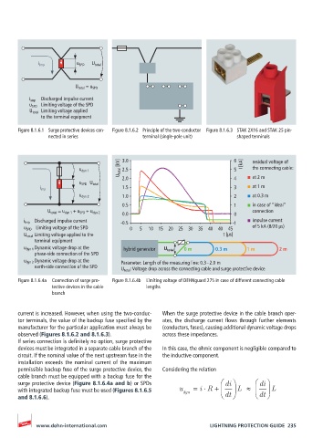
U total [kV] 3.0 6 I [kA] residual voltage of
the connecting cable:
u dyn 1 2.5 5
2.0 4 at 2 m
u SPD U total
i imp 1.5 3 at 1 m
u dyn 2 1.0 2 at 0.3 m
0.5 1 in case of “ideal”
U total = u dyn 1 + u SPD + u dyn 2 connection
0.0 0
i imp Discharged impulse current -0.5 -1 impulse current
u SPD Limiting voltage of the SPD 0 5 10 15 20 25 30 35 40 40 45 of 5 kA (8/20 µs)
U total Limiting voltage applied to the t [µs]
terminal equipment
u dyn 1 Dynamic voltage drop at the hybrid generator U total 0 m 0.3 m 1 m 2 m
phase-side connection of the SPD
u dyn 2 Dynamic voltage drop at the Parameter: Length of the measuring line: 0.3 – 2.0 m
earth-side connection of the SPD U total : Voltage drop across the connecting cable and surge protective device
Figure 8.1.6.4a Connection of surge pro- Figure 8.1.6.4b Limiting voltage of DEHNguard 275 in case of different connecting cable
tective devices in the cable lengths
branch
current is increased. However, when using the two-conduc- When the surge protective device in the cable branch oper-
tor terminals, the value of the backup fuse specified by the ates, the discharge current flows through further elements
manufacturer for the particular application must always be (conductors, fuses), causing additional dynamic voltage drops
observed (Figures 8.1.6.2 and 8.1.6.3). across these impedances.
If series connection is definitely no option, surge protective
devices must be integrated in a separate cable branch of the In this case, the ohmic component is negligible compared to
circuit. If the nominal value of the next upstream fuse in the the inductive component.
installation exceeds the nominal current of the maximum
permissible backup fuse of the surge protective device, the Considering the relation
cable branch must be equipped with a backup fuse for the
surge protective device (Figure 8.1.6.4a and b) or SPDs di di
⋅
with integrated backup fuse must be used (Figures 8.1.6.5 u dyn = i R + L ≈ L
and 8.1.6.6). dt dt
www.dehn-international.com LIGHTNING PROTECTION GUIDE 235