
Page 238 - 35_DS702_E_2014_Lightning_Protection_Guide
P. 238
and the rate of current change (di/dt) for transient processes
of some 10 kA/μs, the dynamic voltage drop U dyn mainly de-
pends on the inductive component.
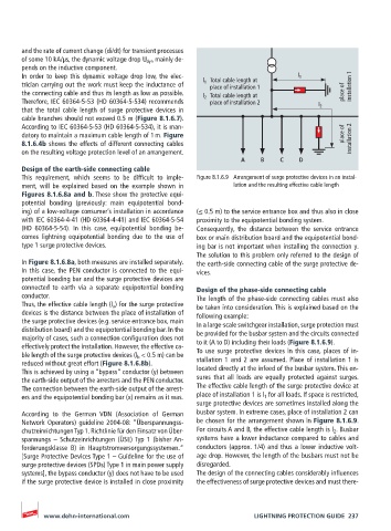
In order to keep this dynamic voltage drop low, the elec- l 1
trician carrying out the work must keep the inductance of l 1 Total cable length at installation 1
place of installation 1
the connecting cable and thus its length as low as possible. l 2 Total cable length at place of
Therefore, IEC 60364-5-53 (HD 60364-5-534) recommends place of installation 2
that the total cable length of surge protective devices in l 2
cable branches should not exceed 0.5 m (Figure 8.1.6.7).
According to IEC 60364-5-53 (HD 60364-5-534), it is man-
datory to maintain a maximum cable length of 1 m. Figure place of installation 2
8.1.6.4b shows the effects of different connecting cables
on the resulting voltage protection level of an arrangement.
A B C D
Design of the earth-side connecting cable
This requirement, which seems to be difficult to imple- Figure 8.1.6.9 Arrangement of surge protective devices in an instal-
ment, will be explained based on the example shown in lation and the resulting effective cable length
Figures 8.1.6.8a and b. These show the protective equi-
potential bonding (previously: main equipotential bond-
ing) of a low-voltage consumer’s installation in accordance (≤ 0.5 m) to the service entrance box and thus also in close
with IEC 60364-4-41 (HD 60364-4-41) and IEC 60364-5-54 proximity to the equipotential bonding system.
(HD 60364-5-54). In this case, equipotential bonding be- Consequently, the distance between the service entrance
comes lightning equipotential bonding due to the use of box or main distribution board and the equipotential bond-
type 1 surge protective devices. ing bar is not important when installing the connection y.
The solution to this problem only referred to the design of
In Figure 8.1.6.8a, both measures are installed separately. the earth-side connecting cable of the surge protective de-
In this case, the PEN conductor is connected to the equi- vices.
potential bonding bar and the surge protective devices are
connected to earth via a separate equipotential bonding Design of the phase-side connecting cable
conductor. The length of the phase-side connecting cables must also
Thus, the effective cable length (l a ) for the surge protective be taken into consideration. This is explained based on the
devices is the distance between the place of installation of following example:
the surge protective devices (e.g. service entrance box, main In a large-scale switchgear installation, surge protection must
distribution board) and the equipotential bonding bar. In the be provided for the busbar system and the circuits connected
majority of cases, such a connection configuration does not to it (A to D) including their loads (Figure 8.1.6.9).
effectively protect the installation. However, the effective ca-
ble length of the surge protective devices (l b < 0.5 m) can be To use surge protective devices in this case, places of in-
reduced without great effort (Figure 8.1.6.8b). stallation 1 and 2 are assumed. Place of installation 1 is
This is achieved by using a “bypass” conductor (y) between located directly at the infeed of the busbar system. This en-
the earth-side output of the arresters and the PEN conductor. sures that all loads are equally protected against surges.
The connection between the earth-side output of the arrest- The effective cable length of the surge protective device at
ers and the equipotential bonding bar (x) remains as it was. place of installation 1 is l 1 for all loads. If space is restricted,
surge protective devices are sometimes installed along the
According to the German VDN (Association of German busbar system. In extreme cases, place of installation 2 can
Network Operators) guideline 2004-08: “Überspannungss- be chosen for the arrangement shown in Figure 8.1.6.9.
chutzeinrichtungen Typ 1. Richtlinie für den Einsatz von Über- For circuits A and B, the effective cable length is l 2 . Busbar
spannungs – Schutzeinrichtungen (ÜSE) Typ 1 (bisher An- systems have a lower inductance compared to cables and
forderungsklasse B) in Hauptstromversorgungssystemen.“ conductors (approx. 1/4) and thus a lower inductive volt-
[Surge Protective Devices Type 1 – Guideline for the use of age drop. However, the length of the busbars must not be
surge protective devices (SPDs) Type 1 in main power supply disregarded.
systems], the bypass conductor (y) does not have to be used The design of the connecting cables considerably influences
if the surge protective device is installed in close proximity the effectiveness of surge protective devices and must there-
www.dehn-international.com LIGHTNING PROTECTION GUIDE 237