
Page 239 - 35_DS702_E_2014_Lightning_Protection_Guide
P. 239
fore be taken into consideration at
L1'
L2' the design stage of the installation!
L3' The contents of the IEC 60364-5-53
PEN (HD 60364-5-534) standard described
F4 F5 F6 above were an important basis for
developing the DEHNventil combined
SEB L1 L1' L2 L2' L3 L3' arrester which combines the require-
F1 – F3
> 125 A gL/gG ments for lightning current and surge
F1 – F3 arresters according to IEC 62305 Part
DEHNventil DV MOD 255 DEHNventil DV MOD 255 DEHNventil DV MOD 255 1-4 (EN 62305 Part 1-4) in a single
F4 – F6
≤ 125 A gL/gG device.
This allows series connection direct-
PEN
ly via the device. Figure 8.1.6.10
MEB shows such a series connection in the
L1 L2 L3PEN
connecting cable form of a detailed wiring diagram.
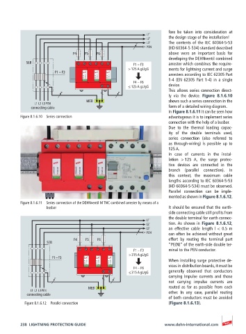
In Figure 8.1.6.11 it can be seen how
Figure 8.1.6.10 Series connection advantageous it is to implement series
connection with the help of a busbar.
Due to the thermal loading capac-
ity of the double terminals used,
series connection (also referred to
as through-wiring) is possible up to
125 A.
In case of currents in the instal-
lation > 125 A, the surge protec-
tive devices are connected in the
branch (parallel connection). In
this context, the maximum cable
lengths according to IEC 60364-5-53
(HD 60364-5-534) must be observed.
Parallel connection can be imple-
mented as shown in Figure 8.1.6.12.
Figure 8.1.6.11 Series connection of the DEHNventil M TNC combined arrester by means of a
busbar It should be ensured that the earth-
side connecting cable still profits from
the double terminal for earth connec-
L1'
L2' tion. As shown in Figure 8.1.6.12,
L3' an effective cable length l < 0.5 m
PEN can often be achieved without great
F4 F5 F6 effort by routing the terminal part
SEB “PE(N)” of the earth-side double ter-
L1 L1' L2 L2' L3 L3'
F1 – F3 minal to the PEN conductor.
> 315 A gL/gG
F1 – F3 When installing surge protective de-
DEHNventil DV MOD 255 DEHNventil DV MOD 255 DEHNventil DV MOD 255
F4 – F6 vices in distribution boards, it must be
≤ 315 A gL/gG generally observed that conductors
carrying impulse currents and those
PEN
not carrying impulse currents are
MEB routed as far as possible from each
L1 L2 L3PEN other. In any case, parallel routing
connecting cable
of both conductors must be avoided
Figure 8.1.6.12 Parallel connection (Figure 8.1.6.13).
238 LIGHTNING PROTECTION GUIDE www.dehn-international.com