
Page 240 - 35_DS702_E_2014_Lightning_Protection_Guide
P. 240
S2
1
1 2 1 2
S3 2
IN (OUT) IN (OUT)
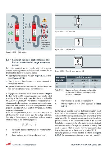
ok DEHNrail DR MOD 255 DEHNrail DR MOD 255 Figure 8.1.7.1 One-port SPD
1 3
Inductive
OUT (IN) 3 4 OUT (IN) 3 4 coupling must
be prevented
on the OUT 2 4
side!
Figure 8.1.7.2 Two-port SPD
Figure 8.1.6.13 Cable routing
8.1.7 Rating of the cross-sectional areas and
backup protection for surge protective
devices
Connecting cables of arresters can be subjected to impulse
currents, operating currents and short-circuit currents. The in- Figure 8.1.7.3 Through-wired one-port SPD
dividual stress depends on various factors:
¨ Type of protective circuit: One-port (Figure 8.1.7.1) / two-
port (Figure 8.1.7.2) Conductor Insulation material
¨ Type of arrester: Lightning current arrester, combined ar- material PVC EPR / XLPE Rubber
rester, surge arrester Cu 115 143 141
¨ Performance of the arrester in case of follow currents: Fol- Al 76 94 93
low current extinction / follow current limitation
Table 8.1.7.1 Material coefficient k for copper and aluminium
conductors with different insulating materials
If surge protective devices are installed as shown in Figure (as per IEC 60364-4-43)
8.1.7.1, the S2 and S3 connecting cables must only be rated
according to the short-circuit protection criteria as outlined in
IEC 60364-4-43 (HD 60364-4-43) and the impulse current car- I Current in case of a direct short-circuit in A
rying capability. The maximum permissible overcurrent protec- k Material coefficient in A ∙ s/mm according to Table
2
tive device, which can be used as backup protection for the 8.1.7.1
arrester in this application, is specified in the data sheet of the
surge protective device. Furthermore, it must be observed that the information about
When installing the devices, it must be ensured that the actu- the maximum permissible overcurrent protective devices in the
ally flowing short-circuit current trips the backup protection. data sheet of the surge protective device is only valid up to the
The rating of the cross-sectional area of the conductor is calcu- value stated for the short-circuit withstand capability of the
lated according to the following equation:
protective device. If the short-circuit current at the place of
installation is greater than the value stated for the short-circuit
2
k S 2 I 2 t withstand capability of the protective device, a backup fuse
must be chosen which is smaller than the maximum backup
t Permissible disconnection time in the event of a short- fuse in the data sheet of the arrester by a ratio of 1:1.6.
circuit in s For surge protective devices installed as shown in Figure
S Cross-sectional area of the conductor in mm 2 8.1.7.2, the maximum operating current must not exceed the
www.dehn-international.com LIGHTNING PROTECTION GUIDE 239