
Page 241 - 35_DS702_E_2014_Lightning_Protection_Guide
P. 241
F1 F1
L1 L1' L1
L2 L2' L2
L3 L3' L3
PEN PEN N
PE
F2
F2
S2
S2
L1 L1' L2 L2' L3 L3'
L1 L2 L3 N
Observe short-
circuit withstand
DEHNventil DV MOD 255 DEHNventil DV MOD 255 DEHNventil DV MOD 255 capability of the DEHNguard DG MOD 275 DEHNguard DG MOD 275 DEHNguard DG MOD 275 DEHNguard DG MOD NPE
busbar
PEN
PE
S3
L1' S3
L2'
MEB
L3' local EB
S3: Required at the supply point
Fuse F1 S2 / mm 2 S3 / mm 2 Fuse F2
DEHNventil DV M TNC 255 A gL / gG A gL / gG Fuse F1 S2 / mm S3 / mm Fuse F2
2
2
25 10 16 --- DEHNguard M TNC 275 A gL / gG A gL / gG
F1 > 315 A gL / gG 35 10 16 --- DEHNguard M TNS 275
40 10 16 --- DEHNguard M TT 275 35 4 6 ---
50 10 16 --- F1 > 125 A gL / gG 40 4 6 ---
F1 63 10 16 ---
80 10 16 --- F1 50 6 6 ---
F2 ≤ 315 A gL / gG 100 16 16 --- 63 10 10 ---
125 16 16 --- F2 ≤ 125 A gL / gG
F1 ≤ 315 A gL / gG 80 10 10 ---
F2 160 25 25 --- F1 ≤ 125 A gL / gG 100 16 16 ---
200 35 35 ---
250 35 35 --- F2 125 16 16 ---
315 50 50 ---
F2 > 315 50 50 ≤ 315 F2 >125 16 16 125
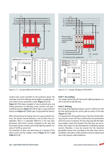
Figure 8.1.7.4 Example: DEHNventil M TNC 255 Figure 8.1.7.5 Example: DEHNguard M TNC/TNS/TT
nominal load current specified for the protective device. The Field 1: No melting
maximum current for through-wiring applies to protective de- The energy injected into the fuse by the lightning impulse cur-
vices which can be connected in series (Figure 8.1.7.3). rent is too low to melt the fuse.
Figure 8.1.7.4 shows examples of cross-sectional areas and
backup protection for lightning current arresters and type 1 Field 2: Melting
combined arresters, Figure 8.1.7.5 for type 2 surge protective The energy of the lightning impulse current is sufficient to melt
devices and Figure 8.1.7.6 for type 3 surge protective devices. the fuse and interrupt the current path by means of the fuse
(Figure 8.1.7.8).
When dimensioning the backup fuses for surge protective de- It is characteristic of the performance of the fuse that the light-
vices, the impulse current behaviour must be taken into con- ning impulse current still flows unaffected by the performance
sideration. There is a noticeable difference in the way fuses of the fuse since it is injected. The fuse trips only after the light-
disconnect short-circuit currents compared to the way they ning impulse current has decayed. Thus, the fuses are not se-
disconnect impulse currents, particularly lightning impulse cur- lective with respect to the disconnection of lightning impulse
rents of 10/350 μs wave form. currents. Therefore, it must be ensured that the maximum
The behaviour of fuses was determined as a function of the permissible backup fuse according to the data sheet and / or
rated current and the impulse current (Figure 8.1.7.7 and installation instructions of the protective device is always used
Table 8.1.7.2). due to the impulse current behaviour.
240 LIGHTNING PROTECTION GUIDE www.dehn-international.com