
Page 24 - 35_DS702_E_2014_Lightning_Protection_Guide
P. 24
ness of the current di/dt. Each parameter tends to dominate a
d different failure mechanism as analysed in detail above.
F
2.6 Lightning current components
F I Figures 2.1.7 and 2.1.8 show the fundamental lightning
current curves and the possible components of upward and
downward flashes as described in the IEC 62305-1 lightning
protection standard.
The total lightning current can be subdivided into individual
i i i i lightning current components:
¨ First positive short stroke
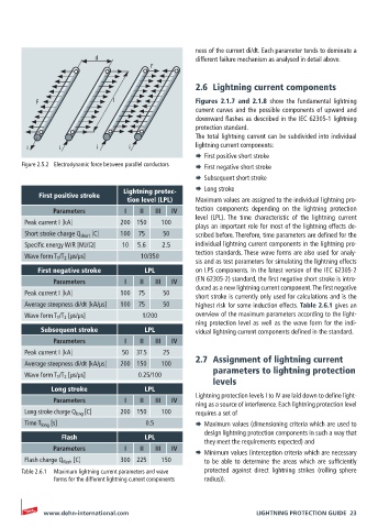
Figure 2.5.2 Electrodynamic force between parallel conductors ¨ First negative short stroke
¨ Subsequent short stroke
Lightning protec- ¨ Long stroke
First positive stroke
tion level (LPL) Maximum values are assigned to the individual lightning pro-
Parameters I II III IV tection components depending on the lightning protection
level (LPL). The time characteristic of the lightning current
Peak current I [kA] 200 150 100
plays an important role for most of the lightning effects de-
Short stroke charge Q short [C] 100 75 50 scribed before. Therefore, time parameters are defined for the
Specific energy W/R [MJ/Ω] 10 5.6 2.5 individual lightning current components in the lightning pro-
tection standards. These wave forms are also used for analy-
Wave form T 1 /T 2 [µs/µs] 10/350
sis and as test parameters for simulating the lightning effects
First negative stroke LPL on LPS components. In the latest version of the IEC 62305-2
Parameters I II III IV (EN 62305-2) standard, the first negative short stroke is intro-
duced as a new lightning current component. The first negative
Peak current I [kA] 100 75 50 short stroke is currently only used for calculations and is the
Average steepness di/dt [kA/µs] 100 75 50 highest risk for some induction effects. Table 2.6.1 gives an
Wave form T 1 /T 2 [µs/µs] 1/200 overview of the maximum parameters according to the light-
ning protection level as well as the wave form for the indi-
Subsequent stroke LPL vidual lightning current components defined in the standard.
Parameters I II III IV
Peak current I [kA] 50 37.5 25
Average steepness di/dt [kA/µs] 200 150 100 2.7 Assignment of lightning current
Wave form T 1 /T 2 [µs/µs] 0.25/100 parameters to lightning protection
levels
Long stroke LPL
Lightning protection levels I to IV are laid down to define light-
Parameters I II III IV
ning as a source of interference. Each lightning protection level
Long stroke charge Q long [C] 200 150 100 requires a set of
Time T long [s] 0.5 ¨ Maximum values (dimensioning criteria which are used to
design lightning protection components in such a way that
Flash LPL
they meet the requirements expected) and
Parameters I II III IV
¨ Minimum values (interception criteria which are necessary
Flash charge Q flash [C] 300 225 150 to be able to determine the areas which are sufficiently
Table 2.6.1 Maximum lightning current parameters and wave protected against direct lightning strikes (rolling sphere
forms for the different lightning current components radius)).
www.dehn-international.com LIGHTNING PROTECTION GUIDE 23