
Page 26 - 35_DS702_E_2014_Lightning_Protection_Guide
P. 26
particularly remarkable. With an average of 8 short strokes
(either superimposed on the long stroke or subsequent to the total current [kA]
long stroke), considerably more impulse currents were record- 0.5
ed than the 3 to 4 subsequent strokes which typically occur in
case of downward flashes. Thus, the 3 to 4 impulse discharges 0.0
per flash stated in the lightning protection standards only ap- -0.5
ply to downward flashes.
For 10 years (2000 to 2009), ALDIS has been recording 10 -1.0
flashes with total charges exceeding the maximum charge val-
ue of 300 As depending on the lightning protection level (LPL). -1.5
These high charge values were recorded only during winter
thunderstorms. In the first measuring period, the mobile sys- -2.0
tem also recorded long strokes during winter thunderstorms
with higher charges than the charges specified for LPL I. -2.5
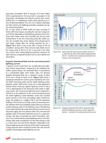
Figure 2.8.2 shows a long stroke with a charge of 405 As 0 100 200 300 400 500 600 700 800
recorded in January 2007. These extreme loads, which exceed time [ms]
the charge value of 300 As of LPL I, may have to be taken
into account when taking lightning protection measures for Figure 2.8.2 Long stroke with superimposed impulse currents of
high structures at exposed locations such as wind turbines and an upward flash with a total charge of approximately
transmitters. 405 As – recorded at the Gaisberg transmission mast
during a winter thunderstorm
Negative downward flash and the associated partial
lightning current
A negative cloud-to-earth flash was recorded during the light- 5
ning current measurements. Compared to the previously de- 0 ALDIS
-5
scribed upward flashes, this downward flash is characterised total current [kA] -10 DEHN
by a considerably higher short strokes value. The detected -15 subsequent
negative downward flash has a maximum current of about -20 M-component
29 kA and a charge of about 4.4 As. Figure 2.8.3 shows a -25 negative
comparison between the current curves recorded by the scien- -30 short stroke
tific ALDIS measuring system and the mobile lightning current
detection system. Both current curves are in good agreement. 20
Another slowly increasing negative lightning current of about 0
5 kA is superimposed on the decreasing short stroke. In light- -20
-40
ning research, this characteristic lightning current component is -60
referred to as M-component. In the second measuring period, partial current [A] power supply line -80
the mobile lightning current detection system also recorded -100
partial currents in one of the low-voltage cables installed be- -120
tween the platform at a height of 80 m and the operations
building at the foot due to the high number of measuring chan- 0 0.2 0.4 0.6 0.8
nels. Between these two installation points, there are numerous time [ms]
parallel discharge paths for the lightning current. The lightning Figure 2.8.3 Negative downward flash with M-component (top)
current splits between the metal mast structure and the numer- and partial lightning current in a power supply line
ous power supply, data and antenna cables. Thus, the measured (below) – recorded at the Gaisberg transmission mast
absolute value of the partial lightning current in a single low-
voltage cable does not provide any useful information. How-
ever, it was verified that the partial lightning current in the low-
voltage cable under consideration has the same polarity as well
as a wave form and current flow duration comparable to the
primary lightning current at the top of the tower. Consequently,
a surge protective device installed to protect this cable must be
capable of discharging partial lightning currents.
www.dehn-international.com LIGHTNING PROTECTION GUIDE 25