
Page 253 - 35_DS702_E_2014_Lightning_Protection_Guide
P. 253
Surge protection for electrical temperature measur- current loop coming from the measuring transducer, but is not
ing equipment shown here for reasons of clarity.
The electrical temperature measurement of media in techno-
logical processes is used in all industrial sectors. The fields of
application can be very different: They range from food pro- 8.2.1 Measuring and control systems
cessing and chemical reactions to air-conditioning systems for Due to the large distance between the measuring sensor and
buildings and building services management systems. A com- the evaluation unit in measuring and control systems, surges
mon characteristic of these processes is that the location of may be injected. The resulting destruction of components and
measured value acquisition is a long way from where the data the failure of complete control units can significantly interfere
is displayed or processed. Due to these long connecting cables, with process technology procedures. The extent of surge dam-
surges, which are not only caused by atmospheric discharges, age caused by a lightning strike often only becomes appar-
can be injected. Therefore, a possible surge protection concept ent weeks later since more and more electronic components
for measuring the temperature with a standard resistance which no longer operate safely have to be replaced. Such kind
thermometer of type Pt 100 will be described in the following. of damage can have serious consequences for the operator
The building where the measuring equipment is located has no who uses a so-called field bus system if all intelligent field bus
external lightning protection system.
components in one segment fail at the same time.
This can be prevented by installing lightning current and surge
The temperature is measured indirectly by measuring the elec- arresters (SPDs) which have to be chosen according to the in-
trical resistance. The Pt 100 sensor has a resistance of 100 Ω at terface.
0 °C. Depending on the temperature, this value varies by about Typical interfaces and the system-specific surge protective de-
0.4 Ω/K. The temperature is measured by injecting a constant
measuring current which causes a voltage drop across the vices can be found in our Surge Protection Catalogue or at
resistance thermometer proportional to the temperature. In www.dehn-international.com.
order to prevent self-heating of the resistance thermometer
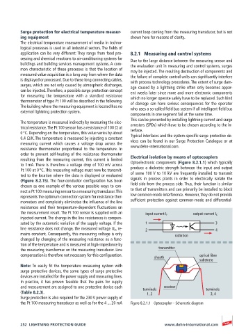
resulting from the measuring current, this current is limited Electrical isolation by means of optocouplers
to 1 mA. There is therefore a voltage drop of 100 mV across Optoelectronic components (Figure 8.2.1.1) which typically
Pt 100 at 0 °C. This measuring voltage must now be transmit- produce a dielectric strength between the input and output
ted to the location where the data is displayed or evaluated of some 100 V to 10 kV are frequently installed to transmit
(Figure 8.2.15). The four-conductor configuration has been signals in process plants in order to electrically isolate the
chosen as one example of the various possible ways to con- field side from the process side. Thus, their function is similar
nect a Pt 100 measuring sensor to a measuring transducer. This to that of transmitters and can primarily be installed to block
represents the optimum connection system for resistance ther- low common-mode interference. However, they do not provide
mometers and completely eliminates the influence of the line sufficient protection against common-mode and differential-
resistances and their temperature-dependent fluctuations on
the measurement result. The Pt 100 sensor is supplied with an input current I F output current I C
injected current. The change in the line resistances is compen-
sated by the automatic variation of the supply voltage. If the 1 3
line resistance does not change, the measured voltage U m re- 2 4
mains constant. Consequently, this measuring voltage is only radiation
changed by changing of the measuring resistance as a func-
tion of the temperature and is measured at high-impedance by
the measuring transformer on the measuring transducer. Line transmitter
compensation is therefore not necessary for this configuration. optical fibre
sheath
substrate
Note: To easily fit the temperature measuring system with
surge protective devices, the same types of surge protective
devices are installed for the power supply and measuring lines.
In practice, it has proven feasible that the pairs for supply
and measurement are assigned to one protective device each terminals receiver terminals
(Table 8.2.3). 1, 2 3, 4
Surge protection is also required for the 230 V power supply of
the Pt 100 measuring transducer as well as for the 4 ... 20 mA Figure 8.2.1.1 Optocoupler – Schematic diagram
252 LIGHTNING PROTECTION GUIDE www.dehn-international.com