
Page 251 - 35_DS702_E_2014_Lightning_Protection_Guide
P. 251
BLITZDUCTOR XT protection module, different nominal volt- protection level must be so low that it is below the specified
ages are given. These are shown in Figure 8.2.4 and Table immunity level of the device to be protected. Therefore, Yel-
8.2.1. low/Line products were subdivided into SPD classes (Table
7.8.2.1) to facilitate coordinated installation of the arresters
8. Does the switching of the decoupling impedances for protecting automation devices. The surge immunity test for
of BLITZDUCTOR XT to the signal circuit have any these devices was taken as a basis for determining the SPD
effects on the signal transmission? class symbols. If, for example, an automation device is tested
Decoupling impedances are integrated to coordinate the pro- with test level 1, the surge protective device may only have a
tection elements in BLITZDUCTOR XT. They are located directly "let-through energy" corresponding to this interference level.
in the signal circuit and may therefore have an effect on it. In practice, this means that automation devices tested with
Particularly in case of current loops (0 – 20 mA, 4 – 20 mA), the test level 4 can only discharge surges without damaging the
maximum load on the signal circuit can be exceeded as soon equipment if the output of the surge protective device has a
as BLITZDUCTOR XT operates if the signal circuit is already voltage protection level according to test level 1, 2, 3, or 4.
being operated at its maximum load. This must be taken into This makes it very easy for the user to choose suitable surge
consideration before installation! protective devices.
9. Which protective effect is required? 10. Shall a one-stage or two-stage protection be
In principle, it is possible to dimension the voltage protection used in the installation?
level for a surge protective device in such a way that it is below Depending on the infrastructure of the building and the pro-
the destruction limit of an automation / telecommunications tection requirements resulting from the lightning protection
equipment. However, the problem with this type of dimension- zone concept, it may be necessary to install lightning cur-
ing consists in the fact that the destruction limit for a termi- rent and surge arresters so that they are spatially separated
nal device is often not known. It is therefore necessary to use or alternately at one point of the installation by means of a
other comparison criteria in this case. As part of the test for combined arrester. In the first case, a BLITZDUCTOR XT with a
electromagnetic compatibility (EMC), electrical and electronic protection module of type BXT ML … B is installed as lightning
equipment must have a certain immunity to pulse-shaped con- current arrester and an upstream arrester as surge arrester. If
ducted interference. The requirements for these tests and the lightning and surge protection measures are required at the
test setups are described in IEC 61000-4-5 (EN 61000-4-5). Dif- same point of the installation, a BLITZDUCTOR XT of type BE...
ferent test levels are defined with respect to the immunity to or BD… can be used.
pulse-shaped interference for the various devices used under
varying electromagnetic environmental conditions. These test Note: The following solution examples show the selection of
levels range from 1 to 4, whereas test level 1 has the lowest surge protective devices of the BLITZDUCTOR XT family with
immunity requirements on the devices to be protected and test the help of the 10 selection criteria (SC). The result of every
level 4 ensures the highest immunity requirements of a device. single selection step is shown in the “intermediate result” col-
For the protective effect of a surge protective device, this umn. The “final result” column shows the effect of the relevant
means that the “let-through energy“ related to the voltage intermediate result on the total result.
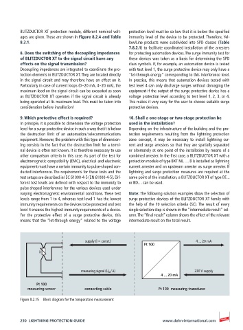
supply (l = const.) 4 ... 20 mA
Pt 100
ϑ
measuring signal (U m / ϑ) 230 V supply
4 ... 20 mA
Pt 100
measuring sensor connecting cable Pt 100 measuring transducer
Figure 8.2.15 Block diagram for the temperature measurement
250 LIGHTNING PROTECTION GUIDE www.dehn-international.com