
Page 254 - 35_DS702_E_2014_Lightning_Protection_Guide
P. 254
mode interference in case of a lightning strike (> 10 kV) above and to adapt it to changing organisational requirements, thus
their transmitter / receiver impulse withstand voltage. facilitating optimum management which increases the profit-
Many designers and operators of such installations by mistake ability of a property.
assume that this also ensures lightning and surge protection.
At this point, it is expressly pointed out that this voltage merely Building automation (BA) has grown out of measuring and
provides the insulation strength between the input and output control systems on the one hand, and centralised instrumenta-
(common-mode interference). This means that, when installed tion and control on the other hand. The function of building au-
in transmission systems, not only the limitation of common- tomation is to automate all technical processes in the building.
mode interference, but also sufficient limitation of differential- Therefore, the complete installation comprising room automa-
mode interference must be ensured. Furthermore, the integra- tion, the M-bus measuring system and the heating, ventilation,
tion of additional decoupling resistors at the output of the SPD air-conditioning and alarm system are networked via powerful
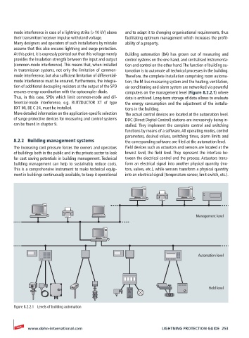
ensures energy coordination with the optocoupler diode. computers on the management level (Figure 8.2.2.1) where
Thus, in this case, SPDs which limit common-mode and dif- data is archived. Long-term storage of data allows to evaluate
ferential-mode interference, e.g. BLITZDUCTOR XT of type the energy consumption and the adjustment of the installa-
BXT ML BE C 24, must be installed. tions in the building.
More detailed information on the application-specific selection The actual control devices are located at the automation level.
of surge protective devices for measuring and control systems DDC (Direct Digital Control) stations are increasingly being in-
can be found in chapter 9. stalled. They implement the complete control and switching
functions by means of a software. All operating modes, control
parameters, desired values, switching times, alarm limits and
8.2.2 Building management systems the corresponding software are filed at the automation level.
The increasing cost pressure forces the owners and operators Field devices such as actuators and sensors are located at the
of buildings both in the public and in the private sector to look lowest level, the field level. They represent the interface be-
for cost saving potentials in building management. Technical tween the electrical control and the process. Actuators trans-
building management can help to sustainably reduce costs. form an electrical signal into another physical quantity (mo-
This is a comprehensive instrument to make technical equip- tors, valves, etc.), while sensors transform a physical quantity
ment in buildings continuously available, to keep it operational into an electrical signal (temperature sensor, limit switch, etc.).
Management level
Automation level
Field level
Figure 8.2.2.1 Levels of building automation
www.dehn-international.com LIGHTNING PROTECTION GUIDE 253