
Page 372 - 35_DS702_E_2014_Lightning_Protection_Guide
P. 372
tomatically detects the operating voltage of the useful sig-
nal and adjusts the voltage protection level to this operating
voltage.
High-voltage-resistant, insulated HVI Conductor
Another possibility to maintain the separation distance s
is to use high-voltage-resistant, insulated HVI Conductors
which allow to maintain a separation distance s up to 0.9 m
in air. HVI Conductors may directly contact the PV system
downstream of the sealing end range. More detailed infor-
mation on the application and installation of HVI Conduc-
tors is provided in this Lightning Protection Guide or in the
relevant installation instructions.
Building with external lightning protection system
with insufficient separation distance s (situation C)
If the roofing is made of metal or is formed by the PV sys-
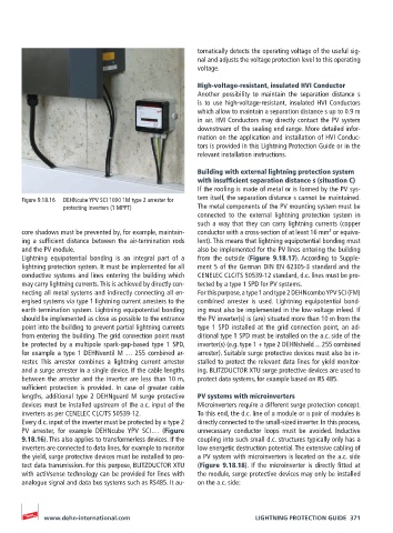
Figure 9.18.16 DEHNcube YPV SCI 1000 1M type 2 arrester for tem itself, the separation distance s cannot be maintained.
protecting inverters (1 MPPT) The metal components of the PV mounting system must be
connected to the external lightning protection system in
such a way that they can carry lightning currents (copper
2
core shadows must be prevented by, for example, maintain- conductor with a cross-section of at least 16 mm or equiva-
ing a sufficient distance between the air-termination rods lent). This means that lightning equipotential bonding must
and the PV module. also be implemented for the PV lines entering the building
Lightning equipotential bonding is an integral part of a from the outside (Figure 9.18.17). According to Supple-
lightning protection system. It must be implemented for all ment 5 of the German DIN EN 62305-3 standard and the
conductive systems and lines entering the building which CENELEC CLC/TS 50539-12 standard, d.c. lines must be pro-
may carry lightning currents. This is achieved by directly con- tected by a type 1 SPD for PV systems.
necting all metal systems and indirectly connecting all en- For this purpose, a type 1 and type 2 DEHNcombo YPV SCI (FM)
ergised systems via type 1 lightning current arresters to the combined arrester is used. Lightning equipotential bond-
earth-termination system. Lightning equipotential bonding ing must also be implemented in the low-voltage infeed. If
should be implemented as close as possible to the entrance the PV inverter(s) is (are) situated more than 10 m from the
point into the building to prevent partial lightning currents type 1 SPD installed at the grid connection point, an ad-
from entering the building. The grid connection point must ditional type 1 SPD must be installed on the a.c. side of the
be protected by a multipole spark-gap-based type 1 SPD, inverter(s) (e.g. type 1 + type 2 DEHNshield ... 255 combined
for example a type 1 DEHNventil M … 255 combined ar- arrester). Suitable surge protective devices must also be in-
rester. This arrester combines a lightning current arrester stalled to protect the relevant data lines for yield monitor-
and a surge arrester in a single device. If the cable lengths ing. BLITZDUCTOR XTU surge protective devices are used to
between the arrester and the inverter are less than 10 m, protect data systems, for example based on RS 485.
sufficient protection is provided. In case of greater cable
lengths, additional type 2 DEHNguard M surge protective PV systems with microinverters
devices must be installed upstream of the a.c. input of the Microinverters require a different surge protection concept.
inverters as per CENELEC CLC/TS 50539-12. To this end, the d.c. line of a module or a pair of modules is
Every d.c. input of the inverter must be protected by a type 2 directly connected to the small-sized inverter. In this process,
PV arrester, for example DEHNcube YPV SCI … (Figure unnecessary conductor loops must be avoided. Inductive
9.18.16). This also applies to transformerless devices. If the coupling into such small d.c. structures typically only has a
inverters are connected to data lines, for example to monitor low energetic destruction potential. The extensive cabling of
the yield, surge protective devices must be installed to pro- a PV system with microinverters is located on the a.c. side
tect data transmission. For this purpose, BLITZDUCTOR XTU (Figure 9.18.18). If the microinverter is directly fitted at
with actiVsense technology can be provided for lines with the module, surge protective devices may only be installed
analogue signal and data bus systems such as RS485. It au- on the a.c. side:
www.dehn-international.com LIGHTNING PROTECTION GUIDE 371