
Page 22 - Arc Guard System - TVOC-2
P. 22
22 ABB ARC GUARD SYSTEM™ – TVOC-2 INSTALLATION AND MAINTENANCE GUIDE
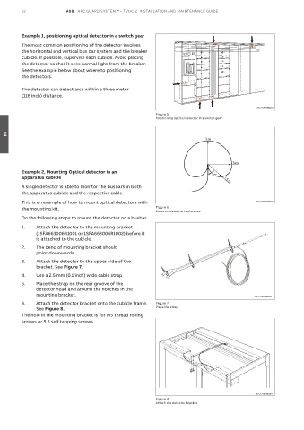
Example 1, positioning optical detector in a switch gear
The most common positioning of the detector involves
the horizontal and vertical bus bar system and the breaker
cubicle. If possible, supervise each cubicle. Avoid placing
the detector so that it sees normal light from the breaker.
See the example below about where to positioning
the detectors.
The detector can detect arcs within a three meter
(118 inch) distance.
1SFC170011M0201
Figure 5
Positioning optical detector in a switch gear
04
3 m
3 m
Example 2, Mounting Optical detector in an
apparatus cubicle 30° 1.5 m
A single detector is able to monitor the busbars in both
the apparatus cubicle and the respective cable.
This is an example of how to mount optical detectors with 1SFC170011M0201
the mounting kit. Figure 6
Detector detect arcs distance
Do the following steps to mount the detector on a busbar.
1. Attach the detector to the mounting bracket
(1SFA663006R1001 or 1SFA663006R1002) before it
is attached to the cubicle.
2. The bend of mounting bracket should
point downwards.
3. Attach the detector to the upper side of the
bracket. See Figure 7.
4. Use a 2.5 mm (0.1 inch) wide cable strap.
5. Place the strap on the rear groove of the
detector head and around the notches in the
mounting bracket. 1SFC170011M0201
6. Attach the detector bracket onto the cubicle frame. Figure 7
See Figure 8. Place the strap
The hole in the mounting bracket is for M5 thread rolling
screws or 5.5 self tapping screws.
1SFC170011M0201
Figure 8
Attach the detector bracket