
Page 128 - 35_DS702_E_2014_Lightning_Protection_Guide
P. 128
Surface earth electrodes must be buried at a depth of at least trodes and earth rods with the same earth resistance are
0.5 m in the form a closed ring. roughly the same.
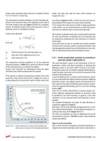
The conventional earthing impedance of earth electrodes de- According to Figure 5.5.15, an earth rod must only have ap-
pends on the maximum value of the lightning current and of proximately half the length of a surface earth electrode.
the earth resistivity (see also Figure 5.5.13). As an approxi- If the conductivity of the ground is better in deep ground than
mation, the effective length of the earth electrode in case of on the surface, e.g. due to ground water, an earth rod is gener-
lightning currents is calculated as follows: ally more cost-effective than a surface earth electrode.
Surface earth electrode: The question of whether earth rods or surface earth electrodes
are more cost-effective in individual cases can frequently only
l = 0.28 î
eff E be answered by measuring the earth resistivity as a function
of the depth.
Earth rod:
Since earth rods are easy to assemble and achieve excellent
l = 0.2 î constant earth resistances without requiring excavation work
eff E and damaging the ground, these earth electrodes are also suit-
able for improving existing earth-termination systems.
l eff Effective length of the earth electrode in m
î Peak value of the lightning current in kA
ρ E Earth resistivity in Ωm 5.5.1 Earth-termination systems in accordance
with IEC 62305-3 (EN 62305-3)
The conventional earthing impedance R st can be calculated The earth-termination system is the continuation of the air-
using the formulas in Table 5.5.1, where the effective length termination systems and down conductors to discharge the
of the earth electrode I eff is used for the length I. lightning current to the earth. Other functions of the earth-
Surface earth electrodes are advantageous when the upper termination system are to establish equipotential bonding be-
soil layers have a lower resistivity than the subsoil.
tween the down conductors and to control the potential in the
vicinity of the building walls.
If the ground is relatively homogeneous (namely if the earth
resistivity at the surface of the earth is roughly the same as It must be observed that a common earth-termination system
in deep ground), the construction costs of surface earth elec- is to be preferred for the different electrical systems (lightning
protection systems, low-voltage systems and telecommunica-
tions systems). This earth-termination system must be connect-
ed to the equipotential bonding system via the main earthing
Earth resistance R A (Ω) 80 surface earth electrode Since the IEC 62305-3 (EN 62305-3) standard requires con-
90
busbar (MEB).
earth rod
sistent lightning equipotential bonding, no particular value
70
is specified for the earth resistance. In general, a low earth
60
mended.
50 resistance (≤ 10 Ω, measured with a low frequency) is recom-
The standard distinguishes two types of earth electrode ar-
ρ E = 400 Ωm
40 rangements, type A and type B.
30 ρ E = 100 Ωm Both type A and B earth electrode arrangements have a mini-
mum earth electrode length I 1 of the earthing conductors ac-
20 cording to the class of LPS (Figure 5.5.1.1)
15 The exact soil resistivity can only be determined by on-site
10
5 measurements using the “WENNER method“ (four-conductor
0 measuring method).
0 5 10 15 20 30 40 50 60 70 80 90 100
Earth electrode length l (m)
Type A earth electrodes
Figure 5.5.15 Earth resistance R A of surface earth electrodes and Type A earth electrode arrangements describe individually ar-
earth rods as a function of the earth electrode length I ranged vertical earth electrodes (earth rods) or horizontal ra-
www.dehn-international.com LIGHTNING PROTECTION GUIDE 127