
Page 129 - 35_DS702_E_2014_Lightning_Protection_Guide
P. 129
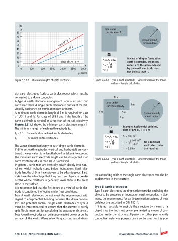
l 1  (m)
                                                             area under
           80                                                consideration A 1          r
           70
           60                      class of LPS I                                 circular area A 2
                                                                                   mean radius r
           50
           40                       class of LPS II
           30
           20                                                             In case of ring or foundation
           10                       class of LPS III-IV     A = A 1  = A 2  earth electrodes, the mean
                                                                A
           0                                                r =   π       radius r of the area enclosed
             0    500   1000  1500  2000  2500  3000                      by the earth electrode must
                                                            r ≥ l 1       not be less than l 1 .
                                              ρ E  (Ωm)
          Figure 5.5.1.1  Minimum lengths of earth electrodes  Figure 5.5.1.2  Type B earth electrode – Determination of the mean
                                                                 radius – Sample calculation


          dial earth electrodes (surface earth electrodes), which must be
          connected to a down conductor.                          12 m
          A  type A  earth  electrode  arrangement  require  at  least  two   area under
          earth electrodes. A single earth electrode is sufficient for indi-  consideration A 1  5 m  r
          vidually positioned air-termination rods or masts.
          A minimum earth electrode length of 5 m is required for class   12 m  5 m  circular area A 2
          of LPS III and IV. For class of LPS I and II the length of the   7 m       mean radius r
          earth electrode is defined as a function of the soil resistivity.
          Figure 5.5.1.1 shows the minimum earth electrode length I 1 .
          The minimum length of each earth electrode is:       7 m     Example: Residential building,
                                                                       class of LPS III, l 1  = 5 m
          I 1  x 0.5  For vertical or inclined earth electrodes
                                                                       A 1  = 109 m 2
          I 1    For radial earth electrodes                 A = A 1  = A 2
                                                             r =   A   r   =   109 m 2  No additional
          The values determined apply to each single earth electrode.  π      3.14  earth electrodes
          If different earth electrodes (vertical and horizontal) are com-  r ≥ l 1  r   = 5.89 m  are required!
          bined, the equivalent total length should be taken into account.
          The minimum earth electrode length can be disregarded if an
          earth resistance of less than 10 Ω is achieved.  Figure 5.5.1.3  Type B earth electrode – Determination of the mean
                                                                 radius – Sample calculation
          In general, earth rods are vertically driven deeply into natu-
          ral soil which typically starts below foundations. Earth elec-
          trode lengths of 9 m have proven to be advantageous. Earth
          rods have the advantage that they reach soil layers in greater   the connecting cable of the single earth electrodes can also be
          depths whose resistivity is generally lower than in the areas   implemented in the structure.
          close to the surface.
          It is recommended that the first metre of a vertical earth elec-  Type B earth electrodes
          trode is considered ineffective under frost conditions.  Type B earth electrodes are ring earth electrodes encircling the
          Type A earth electrodes do not meet the requirements with   object to be protected or foundation earth electrodes. In Ger-
          regard to equipotential bonding between the down conduc-  many, the requirements for earth-termination systems of new
          tors and potential control. Single earth electrodes of type A   buildings are described in DIN 18014.
          must be interconnected to ensure that the current is evenly   If it is not possible to encircle the structure by means of a
          split. This is important for calculating the separation distance s.   closed ring, the ring must be complemented by means of con-
          Type A earth electrodes can be interconnected below or on the   ductors inside the structure. Pipework or other permanently
          surface of the earth. When retrofitting existing installations,   conductive metal components can also be used for this pur-


          128  LIGHTNING PROTECTION GUIDE                            www.dehn-international.com