
Page 242 - 35_DS702_E_2014_Lightning_Protection_Guide
P. 242
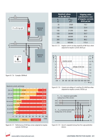
Nominal values       Tripping value
               F1                                          of the NH fuse      calculated in case
          L
         PE                                               I n        I t min  of impulse currents
                                                                     2
          N                                               A           A s        (8/20 µs) kA
                                                                       2
                             1  2
                                                          35          3 030         14.7
              F1 ≤ 25 A gL /gG        electronic          63          9 000         25.4
                             DEHNrail  DR MOD 255  device     100     21 200        38.9
                                                         125         36 000         50.7
                                                         160         64 000         67.6
                             3  4
                                                         200        104 000         86.2
               F1                                        250        185 000         115.0
          L
         PE                                         Table 8.1.7.2  Impulse current carrying capability of NH fuses when
          N                                                   subjected to impulse currents (8/20 µs)
                        F2
                                      electronic
                F1 > 25 A              device        kA  8                               4.0  kV
                             1  2
                                                        7                                3.5
                F2 ≤ 25 A                             I  6     impulse current           3.0  U S
                             DEHNrail  DR MOD 255       5                                2.5
                                                        4                voltage of the fuse  2.0
                                                        3                                1.5
                             3  4
                                                        2                                1.0
       Figure 8.1.7.6  Example: DEHNrail                1                                0.5
                                                        0                                0
                                                        -200 0  200 400 600 800 1000 1200 1400 1600 1800
                                                                                     t             µs

        Nominal currents and design
                                                    Figure 8.1.7.8  Current and voltage of a melting 25 A NH fuse when
                                                              subjected to impulse currents (10/350 µs)
         250 A/1       25 kA               75 kA
         200 A/1      22 kA                70 kA
                                                          F 1  ... F 3  > maximum permissible
        160 A/00     20 kA                 50 kA          backup fuse of the arrester
       100 A/C00  9.5 kA                   25 kA          F 1                             L1
                                                          F 2                             L2
                                                                                          L3
                                                          F 3
        63 A/C00  5.5 kA                   20 kA                                          N
        35 A/C00  4 kA                     15 kA                            F 4 F 5 F 6
                                                        F 4  ... F 6  ≤ maximum permissible   U S
        20 A/C00 1.7 kA                    8 kA         backup fuse of the arrester
               0   10 20 30 40 50 60 70 80 90  100                                        U P
                                            I (kA)
           No melting  Melting    Explosion                                               PE

       Figure 8.1.7.7  Performance of NH fuses when subjected to impulse   Figure 8.1.7.9  Use of a separate backup fuse for surge protective
                currents (10/350 µs)                          devices


            www.dehn-international.com                             LIGHTNING PROTECTION GUIDE  241