
Page 244 - 35_DS702_E_2014_Lightning_Protection_Guide
P. 244
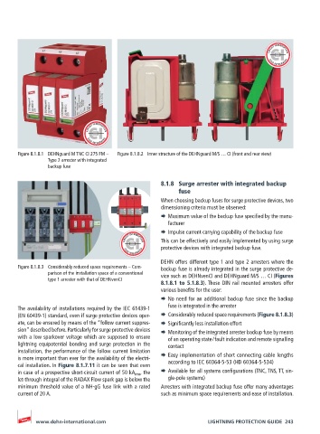
Figure 8.1.8.1  DEHNguard M TNC CI 275 FM –   Figure 8.1.8.2  Inner structure of the DEHNguard M/S … CI (front and rear view)
                Type 2 arrester with integrated
                backup fuse


                                                    8.1.8  Surge arrester with integrated backup
                                                          fuse
                                                    When choosing backup fuses for surge protective devices, two
                                                    dimensioning criteria must be observed:
                                                    ¨  Maximum value of the backup fuse specified by the manu-
                                                       facturer
                                                    ¨  Impulse current carrying capability of the backup fuse
                                                    This can be effectively and easily implemented by using surge
                                                    protective devices with integrated backup fuse.

                                                    DEHN offers different type 1 and type 2 arresters where the
       Figure 8.1.8.3  Considerably reduced space requirements – Com-  backup fuse is already integrated in the surge protective de-
                parison of the installation space of a conventional   vice such as DEHNvenCI and DEHNguard M/S … CI (Figures
                type 1 arrester with that of DEHNvenCI
                                                    8.1.8.1 to 5.1.8.3). These DIN rail mounted arresters offer
                                                    various benefits for the user:
                                                    ¨  No need for an additional backup fuse since the backup
       The availability of installations required by the IEC 61439-1   fuse is integrated in the arrester
       (EN 60439-1) standard, even if surge protective devices oper-  ¨  Considerably reduced space requirements (Figure 8.1.8.3)
       ate, can be ensured by means of the “follow current suppres-  ¨  Significantly less installation effort
       sion” described before. Particularly for surge protective devices   ¨  Monitoring of the integrated arrester backup fuse by means
       with a low sparkover voltage which are supposed to ensure   of an operating state / fault indication and remote signalling
       lightning equipotential bonding and surge protection in the   contact
       installation, the performance of the follow current limitation
       is more important than ever for the availability of the electri-  ¨  Easy implementation of short connecting cable lengths
                                                       according to IEC 60364-5-53 (HD 60364-5-534)
       cal installation. In Figure 8.1.7.11 it can be seen that even
       in case of a prospective short-circuit current of 50 kA rms , the   ¨  Available for all systems configurations (TNC, TNS, TT, sin-
       let-through integral of the RADAX Flow spark gap is below the   gle-pole systems)
       minimum threshold value of a NH-gG fuse link with a rated   Arresters with integrated backup fuse offer many advantages
       current of 20 A.                             such as minimum space requirements and ease of installation.


            www.dehn-international.com                             LIGHTNING PROTECTION GUIDE  243