
Page 245 - 35_DS702_E_2014_Lightning_Protection_Guide
P. 245
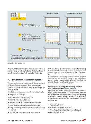
BXT ML4  __ __ _                        discharge capacity     voltage protection level
              BXT ML2  __ __ _                   l in kA                  U in V
                                                  10                       500
                   type key                        8                       400
                                                   6                       300
                                                   4                       200
                      B  = Lightning current arrester  2                   100
                          I imp  = 2.5 kA (10/350 µs) per core
                                                      100  200  300  400  500  600  700  800  100  200  300  400  500  600  700  800
                                                                  t in µs                  t in µs
                                                 l in kA                  U in V
                                                  10                       500
                      B_  = Combined arrester      8                       400
                          I imp  = 2.5 kA (10/350 µs) per core,   6        300
                          However: Same voltage protection   4             200
                          level as surge arrester (M)  2                   100
                                                      100  200  300  400  500  600  700  800  100  200  300  400  500  600  700  800
                                                                  t in µs                  t in µs
                                                 l in kA                  U in V
                      M_  = Surge arrester        10                       500
                          I n  = 2.5 kA (8/20 µs) per core  8              400
                                                   6                       300
                                                   4                       200
             BXT  = BLITZDUCTOR XT                 2                       100
             ML4 = Protection module with integrated LifeCheck (ML), four-pole
             ML2 = Protection module with integrated LifeCheck (ML), two-pole  100  200  300  400  500  600  700  800  100  200  300  400  500  600  700  800
                                                                 t in µs                   t in µs

          Figure 8.2.1  SPD classification

          Moreover, no detailed knowledge of dimensioning criteria for   Protective devices for antenna cables are classified according
          arrester backup fuses is required since the backup fuse is al-  to their suitability for coaxial, balanced or waveguide cable
          ready integrated in and perfectly adapted to the arrester.  systems, depending on the physical design of the antenna ca-
                                                       ble.
                                                       In case of coaxial and waveguide cable systems, the phase
          8.2  Information technology systems          conductor can be connected directly to the equipotential
                                                       bonding system. Earthing sleeves specifically adapted to the
          The main function of arresters is to protect downstream termi-  relevant cable can be used for this purpose.
          nal devices. They also reduce the risk of cable damage.
          The selection of arresters depends, among other things, on the   Procedure for selecting and installing arresters
          following criteria:                          based on the example of BLITZDUCTOR XT
                                                       Opposite to the selection of surge protective devices for power
          ¨  Lightning protection zones of the place of installation, if any  supply systems (see chapter 8.1) where uniform conditions
          ¨  Energies to be discharged                 can be expected with respect to the voltage and frequency
          ¨  Arrangement of the protective devices     in 230/400 V systems, the types of signal to be transmitted
                                                       in automation and measuring and control systems differ with
          ¨  Immunity of the terminal devices          respect to their
          ¨  Differential-mode and / or common-mode protection
          ¨  System requirements, e.g. transmission parameters  ¨  Voltage (e.g. 0 – 10 V)
          ¨  Compliance with product or application-specific standards,   ¨  Current (e.g. 0 – 20 mA, 4 – 20 mA)
            if required                                ¨  Type of signal transmission (balanced, unbalanced)
          ¨  Adaption to environmental / installation conditions  ¨  Frequency (DC, LF, HF)


          244  LIGHTNING PROTECTION GUIDE                            www.dehn-international.com