
Page 246 - 35_DS702_E_2014_Lightning_Protection_Guide
P. 246
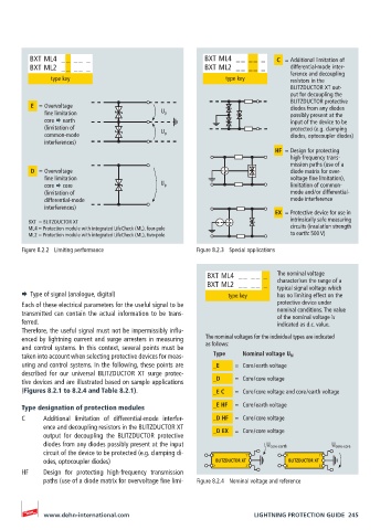
BXT ML4 __ __ _ BXT ML4 __ __ _ C = Additional limitation of
BXT ML2 __ __ _ BXT ML2 __ __ _ differential-mode inter-
ference and decoupling
type key type key resistors in the
BLITZDUCTOR XT out-
put for decoupling the
BLITZDUCTOR protective
E = Overvoltage diodes from any diodes
fine limitation U p possibly present at the
core earth input of the device to be
(limitation of protected (e.g. clamping
common-mode U p diodes, optocoupler diodes)
interferences)
HF = Design for protecting
high-frequency trans-
mission paths (use of a
D = Overvoltage diode matrix for over-
fine limitation voltage fine limitation),
core core U p limitation of common-
(limitation of mode and / or differential-
differential-mode mode interference
interferences)
EX = Protective device for use in
BXT = BLITZDUCTOR XT intrinsically safe measuring
ML4 = Protection module with integrated LifeCheck (ML), four-pole circuits (insulation strength
ML2 = Protection module with integrated LifeCheck (ML), two-pole to earth: 500 V)
Figure 8.2.2 Limiting performance Figure 8.2.3 Special applications
BXT ML4 __ __ _ The nominal voltage
BXT ML2 __ __ _ characterises the range of a
typical signal voltage which
¨ Type of signal (analogue, digital) type key has no limiting effect on the
Each of these electrical parameters for the useful signal to be protective device under
transmitted can contain the actual information to be trans- nominal conditions. The value
of the nominal voltage is
ferred. indicated as d.c. value.
Therefore, the useful signal must not be impermissibly influ-
enced by lightning current and surge arresters in measuring The nominal voltages for the individual types are indicated
and control systems. In this context, several points must be as follows:
taken into account when selecting protective devices for meas- Type Nominal voltage U N
uring and control systems. In the following, these points are _E = Core / earth voltage
described for our universal BLITZDUCTOR XT surge protec-
tive devices and are illustrated based on sample applications _D = Core / core voltage
(Figures 8.2.1 to 8.2.4 and Table 8.2.1). _E C = Core / core voltage and core / earth voltage
Type designation of protection modules _E HF = Core / earth voltage
C Additional limitation of differential-mode interfer- _D HF = Core / core voltage
ence and decoupling resistors in the BLITZDUCTOR XT _D EX = Core / core voltage
output for decoupling the BLITZDUCTOR protective
diodes from any diodes possibly present at the input U core-earth U core-core
circuit of the device to be protected (e.g. clamping di- 1 1‘ 1 1‘
odes, optocoupler diodes) BLITZDUCTOR XT BLITZDUCTOR XT
2 2‘ 2 2‘
HF Design for protecting high-frequency transmission
paths (use of a diode matrix for overvoltage fine limi- Figure 8.2.4 Nominal voltage and reference
www.dehn-international.com LIGHTNING PROTECTION GUIDE 245