
Page 247 - 35_DS702_E_2014_Lightning_Protection_Guide
P. 247
ML4 B 180 ML2 B 180
5 5
12 12 1 1‘
24 24
ML4 BE 36 ML2 BE S 36
48 48
60 2 2‘
180
5 5
12 12
24 24 voltage du/dt = 1 kV/µs
ML4 BD ML2 BD S
48 48
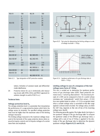
60 Figure 8.2.5 Test setup for determining the limiting voltage at a rate
180 180 of voltage rise du/dt = 1 kV/µs
5
ML4 BC
24
12
ML4 BE C U in V
24 1000
ML4 BE HF 5 ML2 BE HFS 5 900 rate of voltage rise
5 5 800 du/dt = 1 kV/µs
ML4 BD HF ML2 BD HFS 700
24 600
110 110 500
ML4 MY ML2 MY 400 limiting voltage
250 250 300
ML2 BD DL S 15 200
100
ML4 BD EX 24 ML2 BD S EX 24
0
ML4 BC EX 24 0.1 0.2 0.3 0.4 0.5 0.6 0.7 0.8 0.9 1.0 1.1 1.2
ML2 BD HF EX 6 t in µs
Table 8.2.1 Type designation of BXT protection modules Figure 8.2.6 Sparkover performance of a gas discharge tube at
du/dt = 1 kV/µs
tation), limitation of common-mode and differential- Limiting voltage in case of a steepness of the test
mode interference voltage wave form of 1 kV/μs
EX Protective device for use in intrinsically safe measur- This test is carried out to determine the sparkover perfor-
ing circuits with ATEX, IECEx and FISCO approval (in- mance of gas discharge tubes (GDT). These protection ele-
sulation strength to earth of 500 V a.c.) ments have a “switching characteristic”. The functional prin-
ciple of a GTD can be compared to that of a switch whose
Technical data resistance can “automatically“ switch from values > 10 GΩ
(in a non-ignited state) to values < 0.1 Ω (in an ignited state)
when a certain voltage value is exceeded so that the surge
Voltage protection level U p
The voltage protection level is a parameter that characterises applied is almost short-circuited. The voltage value, at which
the performance of a surge protective device which limits the the GDT trips, depends on the rate of rise of the incoming
voltage across its terminals. The specified voltage protection voltage wave (du/dt).
level must be higher than the maximum value of the limiting The following generally applies: The higher du/dt, the higher is
voltages measured. the sparkover voltage of the gas discharge tube. To compare
The limiting voltage measured is the maximum voltage meas- the sparkover values of the different gas discharge tubes, a
ured at the terminals of the surge protective device when ex- voltage with a rate of rise of 1 kV/μs is applied to the elec-
posed to impulse currents and / or impulse voltages of a certain trodes of the gas discharge tube to determine the dynamic
wave form and amplitude. sparkover voltage (Figures 8.2.5 and 8.2.6).
246 LIGHTNING PROTECTION GUIDE www.dehn-international.com